Virtex-5 FPGA ML561 Memory Interfaces Development Board User Guide UG199 (v1.
R Xilinx is disclosing this user guide, manual, release note, and/or specification (the "Documentation") to you solely for use in the development of designs to operate with Xilinx hardware devices. You may not reproduce, distribute, republish, download, display, post, or transmit the Documentation in any form or by any means including, but not limited to, electronic, mechanical, photocopying, recording, or otherwise, without the prior written consent of Xilinx.
Table of Contents Preface: About This Guide Guide Contents . . . . . . . . . . . . . . . . . . . . . . . . . . . . . . . . . . . . . . . . . . . . . . . . . . . . . . . . . . . . . . Additional Documentation . . . . . . . . . . . . . . . . . . . . . . . . . . . . . . . . . . . . . . . . . . . . . . . . . . . Additional Support Resources . . . . . . . . . . . . . . . . . . . . . . . . . . . . . . . . . . . . . . . . . . . . . . . . Conventions . . . . . . . . . . . . . . . . . . . . . . . . . . . . . . . . .
R Seven-Segment Displays . . . . . . . . . . . . . . . . . . . . . . . . . . . . . . . . . . . . . . . . . . . . . . . . . Light Emitting Diodes (LEDs). . . . . . . . . . . . . . . . . . . . . . . . . . . . . . . . . . . . . . . . . . . . . Pushbuttons . . . . . . . . . . . . . . . . . . . . . . . . . . . . . . . . . . . . . . . . . . . . . . . . . . . . . . . . . . Power On or Off Slide Switch . . . . . . . . . . . . . . . . . . . . . . . . . . . . . . . . . . . . . . . . . . . . .
R Appendix B: Bill of Materials Appendix C: LCD Interface General . . . . . . . . . . . . . . . . . . . . . . . . . . . . . . . . . . . . . . . . . . . . . . . . . . . . . . . . . . . . . . . . . . . . 119 Display Hardware Design . . . . . . . . . . . . . . . . . . . . . . . . . . . . . . . . . . . . . . . . . . . . . . . . . . 119 Hardware Schematic Diagram . . . . . . . . . . . . . . . . . . . . . . . . . . . . . . . . . . . . . . . . . . . . . . 120 Peripheral Device KS0713 . . . . . . . . . . . . . . .
R 6 www.xilinx.com Virtex-5 FPGA ML561 User Guide UG199 (v1.
R Preface About This Guide This user guide describes the Virtex®-5 FPGA ML561 Memory Interfaces Development Board. Complete and up-to-date documentation of the Virtex-5 family of FPGAs is available on the Xilinx website at http://www.xilinx.com/virtex5.
R Preface: About This Guide • - Configurable Logic Blocks (CLBs) - SelectIO™ Resources - SelectIO Logic Resources - Advanced SelectIO Logic Resources Virtex-5 FPGA RocketIO GTP Transceiver User Guide This guide describes the RocketIO™ GTP transceivers available in the Virtex-5 LXT and SXT platforms. • Virtex-5 FPGA RocketIO GTX Transceiver User Guide This guide describes the RocketIO GTX transceivers available in the Virtex-5 FXT platform.
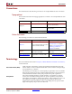
R Conventions Conventions This document uses the following conventions. An example illustrates each convention. Typographical This document uses the following typographical conventions. An example illustrates each convention. Convention Meaning or Use References to other documents See the Virtex-5 Configuration Guide for more information. Emphasis in text The address (F) is asserted after clock event 2. Indicates a link to a web page. http://www.xilinx.
R Preface: About This Guide Hardware Measurements Inter-Symbol Interference (ISI) These measurements are the actual real-time measurements of an eye diagram and a segment of the test pattern (PRBS6) waveform captured on ML561 hardware at the designated probe point using an Agilent scope. As the frequency of operation increases, the signal delay is affected by the data pattern that precedes the current data bit. This is called the inter-symbol interference (ISI) effect.
R Chapter 1 Introduction This chapter introduces the Virtex®-5 FPGA ML561 reference design.
R Chapter 1: Introduction Virtex-5 FPGA ML561 Memory Interfaces Development Board A high-level functional block diagram of the Virtex-5 FPGA ML561 Memory Interfaces Development Board is shown in Figure 1-1.
R Virtex-5 FPGA ML561 Memory Interfaces Development Board Figure 1-2 shows the Virtex-5 FPGA ML561 Development Board and indicates the locations of the resident memory devices. 32-bit DDR400 SDRAM 144 bits wide DDR2 SDRAM DIMM 32-bit DDR2 SDRAM 72 bits wide, up to 4 deep 72-bit QDRII SRAM 36-bit RLDRAM II UG199_c1_02_050106 S Ai lN 10 t hit /d h d F/L Figure 1-2: Virtex-5 FPGA ML561 Development Board Virtex-5 FPGA ML561 User Guide UG199 (v1.2) April 19, 2008 www.xilinx.
R Chapter 1: Introduction 14 www.xilinx.com Virtex-5 FPGA ML561 User Guide UG199 (v1.
R Chapter 2 Getting Started This chapter describes the items needed to configure the Virtex-5 FPGA ML561 Memory Interfaces Development Board. The Virtex-5 FPGA ML561 Development Board is tested at the factory after assembly and should be received in working condition. It is set up to load a bitstream from the CompactFlash card at socket J27 through the System ACE controller (U45).
R Chapter 2: Getting Started 5. Insert the CompactFlash card included in the kit into socket J27 on the Virtex-5 FPGA ML561 Development Board. To select the startup file, check that SW8 is set to position 0. Applying Power to the Board The Virtex-5 FPGA ML561 Development Board is now ready to power on. The Virtex-5 FPGA ML561 Development Board is shipped with a country-specific AC line cord for the universal input 5V desktop power supply.
R Chapter 3 Hardware Description This chapter describes the major hardware blocks on the Virtex-5 FPGA ML561 Development Board and provides useful design consideration.
R SSTL2 _M Chapter 3: Hardware Description SSTL18 MGT Connections FPGA #1 LEDs SSTL2 VTT & VREF SPY A1 DIMM1 DIMM2 DIMM3 DIMM4 DIMM5 DDR FPGA #2 FPGA #1 DDR SPY FPGA #2 Test Header 2 LEDs FPGA #1 LEDs Test Header 1 A1 SSTL18 _M SSTL18 VTT & VREF Config2 12V Banana Jacks ON OFF External CLK Clocks & Buffers Config1 AVTTX AVTRX FBD VCC 7SEG2 DIP2 VCCINT SSTL2 A1 7SEG1 SPY HSTL QDRII 12V Input Jack 5V Banana Jacks ON VVTTR XC DIP1 MGT CLK DDR2 DDR2 AVC CPLL RLDRAM II F
R Hardware Overview Memories Table 3-1 lists the types of memories that the ML561 board supports. Table 3-1: Summary of ML561 Memory Interfaces Memory Type Maximum Speed Data Rate Data Width I/O Standard Data/Strobe Ratios DDR400 SDRAM 200 MHz 400 Mbps 32 SSTL2 8:1 DDR2 DIMM 333 MHz 667 Mbps 144 SSTL18 8:1 DDR2 SDRAM 333 MHz 667 Mbps 32 SSTL18 8:1 QDRII SRAM 300 MHz 1.
R Chapter 3: Hardware Description Wide DIMM1 (XP5) DIMM2 (XP4) DIMM3 (XP3) DIMM4 (XP2) DIMM5 (XP1) Deep DQ and DQS BY0-BY7, CB0_7 DQ and DQS BY8-BY15, CB8_15 Address and Commands DIMM1 Control DIMM2 Control DIMM3 Control DIMM4 Control DIMM5 Control UG199_c3_02_050106 Figure 3-2: DDR2 Deep and Wide DIMM Sockets DDR2 SDRAM Components The ML561 board contains two 333 MHz Micron MT47H32M16CC-3 (16-bit) DDR2 SDRAM components that provide a 32-bit interface to FPGA #1.
R Memory Details Memory Details DDR400 and DDR2 Component Memories The FPGA #1 device on the Virtex-5 FPGA ML561 Development Board is connected to DDR and DDR2 component memories, as shown in Figure 3-3. Figure 3-3 summarizes the distribution of DDR and DDR2 discrete component interface signals among the different banks of the FPGA #1 device.
R Chapter 3: Hardware Description Table 3-3 describes all signals associated with DDR400 Component memories.
R Memory Details DDR2 SDRAM DIMM The FPGA #2 device on the Virtex-5 FPGA ML561 Development Board is connected to DDR2 memories. The DDR2 memory interface includes a 144-bit wide DIMM connection to up to five 240-pin DDR2 DIMM sockets. For the 144-bit wide DIMM datapath, the data bytes are spread across multiple banks of the FPGA #2 device. Figure 3-4 summarizes the distribution of DDR2 DIMM interface signals among the different banks of the FPGA #2 device.
R Chapter 3: Hardware Description Table 3-5 describes all the signals associated with DDR2 DIMM component memories. For the Deep DIMM interface to four DIMMs, the individual dedicated control signals are listed at the bottom of Table 3-5.
R Memory Details QDRII and RLDRAM II Memories Figure 3-5 summarizes the distribution of QDRII and RLDRAM II component interface signals among the different banks of the FPGA #3 device.
R Chapter 3: Hardware Description Table 3-6 describes all the signals associated with QDRII component memories.
R External Interfaces External Interfaces The external interfaces of the Virtex-5 FPGA ML561 Development Board are described in this section. RS-232 The ML561 board provides an RS-232 serial interface using a Maxim MAX3316ECUP device. The maximum speed of this device is 460 Kbps. Hooks are provided to connect and disconnect FPGAs to the RS-232 serial interface, by placing jumpers on headers based on the FPGA involved in the communication.
R Chapter 3: Hardware Description 200 MHz LVPECL Clock The 200 MHz LVPECL clock source is an Epson EG-2121CA200M-PCHS oscillator (Y1) with a differential output. The oscillator runs at 200 MHz ± 100 PPM with an operating voltage of 2.5V ±5%. This output is fed into an ICS853006 LVPECL buffer for generating a separate differential copy for each FPGA as well as a test point (P59).
R External Interfaces Table 3-12: FPGA Slow Clock Sources FPGA Signal Name 1 FPGA1_LOW_FREQ_CLK 2 FPGA2_LOW_FREQ_CLK 3 FPGA3_LOW_FREQ_CLK 33 MHz System ACE Controller Oscillator A single-ended 33 MHz Epson SG-8002CA oscillator is provided on the board (Y3) as a clock source for System ACE functionality. GTP Clocks Two SMA connectors are provided for the input of an off-board differential clock (J16 and J21).
R Chapter 3: Hardware Description Seven-Segment Displays One seven-segment display per FPGA (for a total of three) is available for use. The red Stanley-Electric NAR131SB displays are active Low, using seven inputs to display a character or number plus another input for a decimal point.
R External Interfaces Power On or Off Slide Switch The power on or off slide switch is a DPST slide switch used to apply input power to the board. While the board contains two such switches, the 5V switch is primarily used to supply 5V power to the board, whereas the 12V switch is available for testing only. Soft Touch Probe Points Soft Touch E5396A Probeless connection points are provided for monitoring FPGA #2 and FPGA #3 test signals with a compatible Agilent logic analyzer.
R Chapter 3: Hardware Description Table 3-15: Power Measurement Header Pins (P102) (Continued) Header Signal Power Header Pin # VCC1V8_SENSE+ 13 VCC1V8_SENSE- 14 VCC1V8_MON 15 VCC1V5_SENSE+ 17 VCC1V5_SENSE- 18 VCC1V5_MON 19 VCC2V6_SENSE+ 21 VCC2V6_SENSE- 22 VCC2V6_MON 23 VCC5_SENSE+ 25 VCC5_SENSE- 26 VCC5_MON 24 VCC5 20 GND 4 GND 8 GND 12 GND 16 Liquid Crystal Display Connector Previous memory boards such as the ML461 had a DisplaytechQ 64128E-FC-BC-3LP 64x128 LCD pane
R OFF Power Regulation A1 QDRII 12V Input Jack 5V Banana Jacks ON 7SEG1 SPY HSTL RLDRAM II FPGA3 12V -> 5V QDRII RLDRAM II SPY Test Header 3 Serial Header VCCAUX / VCCO RESET HSTL VTT & VREF System ACE Controller JTAG Test Header OFF 3.3V FPGA3 LEDs 5V Input Jack RS232 Driver Config3 7SEG3 DIP3 Pwr Measure Header LCD Connector HSTL PROG USB JTAG LCD UG199_c3_08_050106 Figure 3-8: LCD Panel Connector for Possible LCD Support The product specification at http://www.
R Chapter 3: Hardware Description also be supplied from a bench supply using the two banana jacks: J25 (RED) for +5V and J24 (BLACK) for GND. The Rev-A assembly of the Virtex-5 FPGA ML561 Development Board does not support the +12V input via jack J23 or via banana jacks J18 (RED) for +12V and J17 (BLACK) for GND. The memory and FPGAs use separate power supplies for SSTL18, HSTL, and SSTL2, respectively.
R Power Regulation The FPGA can drive VMARGIN_DN_xxxx_N and VMARGIN_UP_xxxx_N signals, where xxxx indicates one of the six main power regulators: SSTL2, HSTL, SSTL18, VCC1V0, VCC2V5, and VCC3V3.
R Chapter 3: Hardware Description Table 3-18 summarizes the inhibit headers.
R Board Design Considerations For Write data and terminations at the memory, if the trace length from the receiver pin to the termination resistor can be guaranteed to be within 0.3 inches, then the fly-by termination scheme is implemented. Otherwise, the non-fly-by termination topology is implemented for Write data at the memory end. The physical dimensions of the raw PCB are 12.75 inches x 11.75 inches.
R Chapter 3: Hardware Description Table 3-19 shows the details of the dielectric material and construction for each layer and the controlled impedance values for the signal layers.
R Chapter 4 Electrical Requirements This chapter provides the electrical requirements for the Virtex-5 FPGA ML561 Development Board. It contains the following sections: • “Power Consumption” • “FPGA Internal Power Budget” Power Consumption Table 4-1 lists the operating voltages, maximum currents, and power consumption used by the ML561 board devices. The Virtex-5 FPGA ML561 Development Board has provisions for two power inputs: a 5V power supply and a 12V power supply.
R Chapter 4: Electrical Requirements Table 4-1: ML561 Power Consumption Device Description Quantity Voltage (V) Current Power (mA) (W) Source Total Available Power 5V Power Supply 1 5.0 8000 40.0 Bellus Power SPD-050-5 12V Power Supply 1 12.0 5000 60.0 CUI DTS120500U XC5VLX50T-FFG1136: FPGA #1 (DDR400) 1 1.0, 2.5, 2.6 1887 3.7 DDR x16 Memory 2 2.6 210 1.1 Micron DDR Component Data Sheet DDR Comp VTT Termination 60 1.2 16 1.2 All signals.
R Table 4-1: Power Consumption ML561 Power Consumption (Continued) Device Description Quantity Voltage (V) Current Power (mA) (W) Source Power Modules Capacity VCCINT Power Plane (1.0V) 1 1.00 15000 15.0 HSTL FPGA Power Plane (1.8V) 1 1.80 15000 27.0 HSTL Memory Power Plane (1.8V) 1 1.80 6000 10.8 TI PTH05000 6A Module Data Sheet HSTL _VREF Power Plane (0.9V) 1 0.90 3000 2.7 Fairchild FN6555 Data Sheet SSTL18 FPGA Power Plane (1.8V) 1 1.80 15000 27.
R Chapter 4: Electrical Requirements Table 4-2 lists the 12 different power planes on the Virtex-5 FPGA ML561 Development Board. For the SSTL2, SSTL18, and HSTL power, separate power modules are implemented for VCCO to FPGA, and VDD to memory, allowing for ease of power measurement for the FPGAs. The power modules for VCCO inputs are implemented with TI PTH05010 modules, which have provisions for ± 5% voltage margining pins. Table 4-2: Power Planes VRM REFDES Stack-Up Layer VCCINT Power Plane (1.
R Power Consumption current can support a voltage swing of up to (16 mA * 50Ω) = 800 mV, which is sufficient to meet the output voltage specifications for SSTL18, SSTL2, and HSTL18 I/O standards. Table 4-3 separates the power consumption information from Table 4-1 according to the nine TI power modules for the first set of nine power planes and the three Fairchild regulators for the VTT power planes.
R Chapter 4: Electrical Requirements Table 4-3: ML561 Power Plane Capacities (Continued) Device Description SSTL18 FPGA Power Plane (1.8V) Capacity Quantity Excess Voltage Current Power Power (V) (mA) (W) (W) TI PTH05010 15A Module Data Sheet 1 1.8 15000 27.0 2 1.8 250 0.9 Micron DDR2 Component Data Sheet DDR2 DIMM 2 1.8 1755 6.3 Micron DDR2 DIMM Data Sheet SSTL18_Mem Power Plane (1.8V) Capacity 1 1.8 6000 10.8 DDR2 Comp VTT Termination 25 1.2 16 0.
R Table 4-3: Power Consumption ML561 Power Plane Capacities (Continued) Device Description System ACE Controller 33 MHz Oscillator 3.3V Power Plane Capacity Quantity Excess Voltage Current Power Power (V) (mA) (W) (W) 1 3.3 200 0.7 DS080, System ACE CompactFlash Solution 2 3.3 45 0.3 Epson SG-8002CA Data Sheet 1 3.3 15000 49.5 Total Power Consumed 12V-to-5V Power Module Capacity Source 47.8 TI PTH05010 15A Module Data Sheet 6.8 TI PTH12010 12A Module Data Sheet 53.2 1 5.
R Chapter 4: Electrical Requirements FPGA Internal Power Budget Table 4-4 summarizes power consumption estimates by each of the three XC5VLX50T-FFG1136 FPGAs on the Virtex-5 FPGA ML561 Development Board. This estimate derives the FPGA utilization information from the respective map report of a fully configured reference design.
R Chapter 5 Signal Integrity Recommendations Termination and Transmission Line Summaries The following are common recommendations for the signal termination scheme to all external memories implemented on the Virtex-5 FPGA ML561 Development Board: • Single-ended signals: Simulation indicates that for a single-ended signal, there is no significant performance difference for a signal with split termination of 100Ω + 100Ω between VDD and GND versus the VTT termination of 50Ω to the VREF voltage.
R Chapter 5: Signal Integrity Recommendations Table 5-1: DDR400 SDRAM Component Terminations Signal FPGA Driver Termination at FPGA Data (DQ) SSTL2_II_DCI No termination 50Ω pull-up to 1.3V Data Strobe (DQS) SSTL2_II_DCI No termination 50Ω pull-up to 1.3V Clock (CK, CK) SSTL2_II No termination 100Ω differential termination between pair Address (A, BA) SSTL2_II No termination 50Ω pull-up to 1.
R Table 5-4: Termination and Transmission Line Summaries QDRII SRAM Terminations Signal FPGA Driver Termination at FPGA Write Data (D) HSTL_I_18 No termination 50Ω pull-up to 0.9V Read Data (Q) HSTL_I_DCI_18 No termination No termination HSTL_I_18 No termination 50Ω pull-up to 0.9V HSTL_I_DCI_18 No termination No termination Clock (CK, CK) HSTL_I_18 No termination 100Ω differential termination between pair Address (A, BA) HSTL_I_18 No termination 50Ω pull-up to 0.
R Chapter 5: Signal Integrity Recommendations 50 www.xilinx.com Virtex-5 FPGA ML561 User Guide UG199 (v1.
R Chapter 6 Configuration This chapter provides a brief description of the FPGA configuration methods used on the Virtex-5 FPGA ML561 Development Board. This chapter contains the following sections: • “Configuration Modes” • “JTAG Chain” • “JTAG Port” • “Parallel IV Cable Port” • “System ACE Interface” Configuration Modes The Virtex-5 FPGA ML561 Memory Interfaces Development Board includes several options to configure the Virtex-5 FPGAs.
R Chapter 6: Configuration Table 6-1: Configuration Modes (Continued) Mode Jumpers(3,4) Mode System ACE CF Card XCONFIG P72 JTAG P114 — — 5 -> 6 (M2) 3 -> 4 (M1) 1 -> 2 (M0) 1 1 1 Notes: 1. 2. 3. 4. X = Supported. — = Not applicable. Corresponding jumper position is Closed. Corresponding jumper position is Open. JTAG Chain Four devices (the System ACE chip and three XC5VLX50T-FFG1136 FPGAs) are connected via a JTAG chain on the Virtex-5 FPGA ML561 Development Board.
R System ACE Interface Table 6-2 shows the System ACE interface signal names, descriptions, and pin assignments. Table 6-2: System ACE Interface Signal Descriptions System ACE Pin Number Virtex-5 FPGA ML561 User Guide UG199 (v1.
R Chapter 6: Configuration 54 www.xilinx.com Virtex-5 FPGA ML561 User Guide UG199 (v1.
R Chapter 7 ML561 Hardware-Simulation Correlation This chapter contains the following sections: • “Introduction” • “Test Setup” • “Signal Integrity Correlation Results” • “Summary and Recommendations” • “How to Generate a User-Specific FPGA IBIS Model” Introduction Signal integrity (SI) simulation is a very powerful tool that predicts the quality of signal at the receiver. The quality of signal at the I/O buffer of the receiver device is most important to the system designer.
R Chapter 7: ML561 Hardware-Simulation Correlation illustrated here for these signals can be easily adopted to perform SI analysis for any other memory interface signal on the ML561 board.
R Test Setup strobe, a random value can be applied to data bits from one cycle to another. A 63-bit PRBS6 (1) (PRBS of order 6) test pattern stimulus is used for this analysis. The value of this PRBS6 string is 63’h03F5_66ED_2717_9461, that is: 63’b000001111110101011001101110110100100111000101111001010001100001. The HyperLynx stimulus setup is for: a 2-sequence repeat, 10 bits skipped, 1 eye, and 0% jitter.
R Chapter 7: ML561 Hardware-Simulation Correlation VDDQ VOH(dc) VOH(ac) VIH(ac) VIH(dc) VREF VIL(dc) VIL(ac) VOL(ac) VOL(dc) VSS UG199_c7_02_062707 Figure 7-2: ♦ ♦ Two Triangular Eye Mask Definitions for VIH and VIL DDR2 mask (for nominal VDDQ = 1.8V and VREF = 0.9V): - VIH(ac)-min = VREF + 200 mV = 1.1V - VIH(dc)-min = VREF + 125 mV = 1.025V - VIL(ac)-max = VREF – 200 mV = 0.7V - VIL(dc)-max = VREF – 125 mV = 0.775V QDRII mask (for nominal values of VDDQ = 1.8V and VREF = 0.
R Signal Integrity Correlation Results DDR2 Component Write Operation This subsection shows the test results for the DDR2_DQ_BY2_B3 signal from FPGA1 (U7) to the DDR2 memory component (U12) measured at 333 MHz (667 Mb/s), where the unit interval (UI) = 1.5 ns. U12.D3 28.5 ohms 3.579 ps 0.022 in DDR2_DQ_BY2_B3 49.0 ohms 24.721 ps 0.164 in DDR2_DQ_BY2_B3 71.0 ohms 27.482 ps AutoPadstk_3 TL2 MT47H32M16CC_… DQ11 TL4 TL3 DDR2_D… DDR2_D… C9 58.3 ohms 25.244 ps AutoPadstk_19 49.1 ohms 47.132 ps 0.
R Chapter 7: ML561 Hardware-Simulation Correlation DDR2 DQ is a bidirectional signal. To perform hardware measurements for a Write operation that is not interrupted by a Read response or a Refresh operation, the testbench on FPGA1 is controlled by DIP switches (SW2) as indicated in Table 7-3. Table 7-3: DIP[1:2] Settings Setting 60 Description 2’b00 or 2’b11 Normal alternating Write/Read sequence 2’b01 Write only, Refresh disabled 2’b10 Write once, then Read only, Refresh disabled www.xilinx.
R Signal Integrity Correlation Results UG199_c7_04_071107 Figure 7-4: DDR2 Component Write HW Measurement - Eye Scope Shot at Probe Point (DDR2 Memory Via) 1800.0 1600.0 1400.0 Voltage (mV) 1200.0 1000.0 800.0 600.0 400.0 200.0 0.000 Probe 3:C9.1 (at pin) -200.0 0.000 400.0 800.0 1200.0 Time (ps) ♦ ♦ ♦ ♦ Figure 7-5: 1600.0 UG199_c7_05_070907 333 MHz, Slow, PRBS6, 81.5% UI Cursor 1: 1.1028V, 123.6 ps Cursor 2: 1.0253V, 1.3458 ns Delta Voltage = 77.5 mV, Delta Time = 1.2222 ns (81.
R Chapter 7: ML561 Hardware-Simulation Correlation UG199_c7_06_071107 Figure 7-6: DDR2 Component Write HW Measurement - Waveform Scope Shot at Probe Point (DDR2 Memory Via) 1800.0 1600.0 1400.0 Voltage (mV) 1200.0 1000.0 800.0 600.0 400.0 200.0 0.000 Probe 3:C9.1 (at pin) -200.0 65.000 75.000 85.000 Time (ns) Figure 7-7: 62 95.000 105.000 UG199_c7_07_070907 DDR2 Component Write Correlation - Waveform Scope Shot at Probe Point (Slow Corner) www.xilinx.
R Signal Integrity Correlation Results 1800.0 1600.0 1400.0 1200.0 Voltage (mV) 1000.0 800.0 600.0 400.0 200.0 Probe 1:U12.D3 (at die) 0.000 -200.0 -200.0 200.0 600.0 1000.0 Time (ps) ♦ ♦ ♦ ♦ Figure 7-8: 1400.0 1800.0 UG199_c7_08_071007 333 MHz, Slow, PRBS6, 84.5% UI Cursor 1: 1.1007V, 123.7 ps Cursor 2: 1.0253V, 1.3921 ns Delta Voltage = 75.4 mV, Delta Time = 1.2684 ns (84.5% UI) DDR2 Component Write Extrapolation - Eye Scope Shot at Receiver IOB (Slow Corner) 1800.0 1600.0 1400.
R Chapter 7: ML561 Hardware-Simulation Correlation 1900.0 1700.0 1500.0 Voltage (mV) 1300.0 1100.0 900.0 700.0 500.0 300.0 100.0 Probe 1:U12.D3 (at die) -100.0 800.0 1200.0 2000.0 1600.0 2400.0 Time (ps) ♦ ♦ ♦ ♦ 2800.0 UG199_c7_10_071007 333 MHz, Fast, PRBS6, 92.5% UI Cursor 1: 701.2 mV, 1.0026 ns Cursor 2: 774.6 mV, 2.3908 ns Delta Voltage = 73.4 mV, Delta Time = 1.3883 ns (92.5% UI) Figure 7-10: DDR2 Component Write Extrapolation - Eye Scope Shot at Receiver IOB (Fast Corner) 1900.0 1700.
R Signal Integrity Correlation Results DDR2 Component Read Operation This subsection shows the test results for the DDR2_DQ_BY2_B3 signal from the DDR2 memory component (U12) to FPGA1 (U7) measured at 333 MHz (667 Mb/s), where the unit interval (UI) = 1.5 ns. U12.D3 TL2 TL3 28.5 ohms MT47H64M8CB-3 3.579 ps 0.022 in DQ3 DDR2_DQ_BY2_B3 TL4 49.0 ohms 24.721 ps 0.164 in DDR2_DQ_BY2_B3 71.0 ohms 27.482 ps AutoPadstk_3 DDR2_D… 22.9 fF TL8 DDR2_D… C9 22.9 fF 500.0 fF TL9 58.3 ohms 25.
R Chapter 7: ML561 Hardware-Simulation Correlation UG199_c7_13_071107 Figure 7-13: DDR2 Component Read HW Measurement - Eye Scope Shot at Probe Point (FPGA1 Via) 1900.0 1700.0 1500.0 1300.0 Voltage (mV) 1100.0 900.0 700.0 500.0 300.0 100.0 Probe 3:C7.1 (at pin) -100.0 800.0 1200.0 1600.0 2000.0 Time (ns) ♦ ♦ ♦ ♦ Figure 7-14: 66 2400.0 2800.0 UG199_c7_14_071107 333 MHz, Slow, PRBS6, 85.9% UI Cursor 1: 697.1 mV, 1.2345 ns Cursor 2: 774.6 mV, 2.5191 ns Delta Voltage = 77.5 mV, Delta Time = 1.
R Signal Integrity Correlation Results UG199_c7_15_071107 Figure 7-15: DDR2 Component Read HW Measurement - Waveform Scope Shot at Probe Point (FPGA1 Via) 1900.0 Probe 3:C7.1 (at pin) 1700.0 1500.0 Voltage (mV) 1300.0 1100.0 900.0 700.0 500.0 300.0 100.0 -100.0 65.000 75.000 85.000 Time (ns) Figure 7-16: 95.000 105.000 UG199_c7_16_071007 DDR2 Component Read Correlation - Waveform Scope Shot at Probe Point (Slow Corner) Virtex-5 FPGA ML561 User Guide UG199 (v1.2) April 19, 2008 www.xilinx.
R Chapter 7: ML561 Hardware-Simulation Correlation 1900.0 Probe 1:U7.P25 (at die) 1700.0 1500.0 Voltage (mV) 1300.0 1100.0 900.0 700.0 500.0 300.0 100.0 -100.0 800.0 1200.0 1600.0 2000.0 2400.0 Time (ps) ♦ ♦ ♦ ♦ Figure 7-17: 2800.0 UG199_c7_17_071007 333 MHz, Slow, PRBS6, 85.5% UI Cursor 1: 1.0988V, 1.2170 ns Cursor 2: 1.0254V, 2.5029 ns Delta Voltage = 73.4 mV, Delta Time = 1.2859 ns (85.5% UI) DDR2 Component Read Extrapolation - Eye Scope Shot at Receiver IOB (Slow Corner) 1800.0 1600.
R Signal Integrity Correlation Results 1900.0 1700.0 1500.0 1300.0 Voltage (mV) Probe 1:U7.P25 (at die) 1100.0 900.0 700.0 500.0 300.0 100.0 -100.0 800.0 1200.0 1600.0 2000.0 2400.0 Time (ps) ♦ ♦ ♦ ♦ 2800.0 UG199_c7_19_071007 333 MHz, Fast, PRBS6, 88% UI Cursor 1: 701.2 mV, 1.0772 ns Cursor 2: 774.6 mV, 2.3980 ns Delta Voltage = 73.4 mV, Delta Time = 1.3208 ns (88% UI) Figure 7-19: DDR2 Component Read Extrapolation - Eye Scope Shot at Receiver IOB (Fast Corner) Probe 1:U7.P25 (at die) 1900.
R Chapter 7: ML561 Hardware-Simulation Correlation DDR2 DIMM Write Operation This subsection shows the test results for the DDR2_DIMM_DQ_BY2_B3 signal from FPGA2 (U5) to the DDR2 DIMM (XP2) measured at 333 MHz (667 Mb/s), where the unit interval (UI) = 1.5 ns. 49.8 ohms 94.605 ps 0.606 in DDR2_DIMM_DQ_... U3_B01.J1 59.8 ohms 3.590 ps 0.022 in MDQ19_B01 TL1 59.8 ohms 31.503 ps 0.195 in MDQ19_B01 59.8 ohms 78.962 ps 0.490 in MDQ19_B01 TL5 TL11 RN6_B01 22.0 ohms 59.8 ohms 10.373 ps 0.
R Table 7-7: Signal Integrity Correlation Results DDR2 DIMM Write Operation Correlation Results DVW (%UI) ISI (% UI) Noise Margin (VIH + VIL) = Total (% of VREF) Overshoot / Undershoot Margin (% of VREF) Hardware at Probe Point 942 ps (62.8%) (300 + 200) = 500 ps (110 + 100) = 210 mV (620 + 620) = 1240 mV (33.3%) (23.3%) (137.7%) Simulation correlation at memory via (C13) slow-weak corner 1.16 ns (77.3%) (80 + 54) = 134 ps (172 + 150) = 322 mV (606 + 636) =1242 mV (8.9%) (35.
R Chapter 7: ML561 Hardware-Simulation Correlation UG199_c7_22_071107 Figure 7-22: DDR2 DIMM Write HW Measurement - Eye Scope Shot at Probe Point #1 (DDR2 Memory Via) 1800.0 1600.0 1400.0 1200.0 Voltage (mV) 1000.0 800.0 600.0 400.0 200.0 0.000 -200.0 800.0 Probe 3:C13.1 (at pin) 1200.0 1600.0 2000.0 Time (ps) ♦ ♦ ♦ ♦ Figure 7-23: 72 2400.0 2800.0 UG199_c7_23_070907 333 MHz, Slow, PRBS6, 77% UI Cursor 1: 1.1004V, 1.2553 ns Cursor 2: 1.0253V, 2.4105 ns Delta Voltage = 75.
R Signal Integrity Correlation Results UG199_c7_24_071107 Figure 7-24: DDR2 DIMM Write HW Measurement - Waveform Scope Shot at Probe Point #1 (DDR2 Memory Via) 1800.0 1600.0 1400.0 Voltage (mV) 1200.0 1000.0 800.0 600.0 400.0 200.0 0.000 -200.0 95.000 Probe 3:C13.1 (at pin) 105.000 115.000 125.000 Time (ns) Figure 7-25: 135.000 145.000 UG199_c7_23_071007 DDR2 DIMM Write Correlation - Waveform Scope Shot at Probe Point #1 (Slow Corner) Virtex-5 FPGA ML561 User Guide UG199 (v1.
R Chapter 7: ML561 Hardware-Simulation Correlation 1800.0 1600.0 1400.0 1200.0 Voltage (mV) 1000.0 800.0 600.0 400.0 200.0 0.000 Probe 6:U3_B01.J1 (at die) -200.0 1000.0 1400.0 1800.0 2200.0 Time (ps) ♦ ♦ ♦ ♦ 2600.0 UG199_c7_26_071007 333 MHz, Slow, PRBS6, 82% UI Cursor 1: 1.1028V, 1.2399 ns Cursor 2: 1.0253V, 2.4671 ns Delta Voltage = 77.5 mV, Delta Time = 1.2272 ns (82% UI) Figure 7-26: DDR2 DIMM Write Extrapolation - Eye Scope Shot at Receiver IOB (Slow Corner) 1800.0 1600.0 1400.
R Signal Integrity Correlation Results 1800.0 1600.0 1400.0 1200.0 Voltage (mV) 1000.0 800.0 600.0 400.0 200.0 0.000 -200.0 400.0 Probe 6:U3_B01.J1 (at die) 800.0 1200.0 1600.0 2000.0 Time (ps) ♦ ♦ ♦ ♦ Figure 7-28: 2400.0 UG199_c7_28_071007 333 MHz, Fast, PRBS6, 88% UI Cursor 1: 1.1004V, 646.3 ps Cursor 2: 1.0273V, 1.9659 ns Delta Voltage = 73.1 mV, Delta Time = 1.3196 ns (88% UI) DDR2 DIMM Write Extrapolation - Eye Scope Shot at Receiver IOB (Fast Corner) 1800.0 1600.0 1400.
R Chapter 7: ML561 Hardware-Simulation Correlation DDR2 DIMM Read Operation This subsection shows the test results for the DDR2_DIMM_DQ_BY2_B3 signal from the DDR2 DIMM (XP2) to FPGA2 (U5) measured at 333 MHz (667 Mb/s), where the unit interval (UI) = 1.5 ns. U3_B01.J1 59.8 ohms 3.590 ps 0.022 in MDQ19_B01 TL1 MT47H64M8CB_C... DQ6 59.8 ohms 31.503 ps 0.195 in MDQ19_B01 59.8 ohms 78.962 ps 0.490 in MDQ19_B01 TL5 RN6_B01 TL11 22.0 ohms 49.8 ohms 94.605 ps 0.606 in DDR2_DIMM_DQ_... 59.8 ohms 10.
R Signal Integrity Correlation Results UG199_c7_31_071107 Figure 7-31: DDR2 DIMM Read HW Measurement - Eye Scope Shot at Probe Point (FPGA1 Via) 1900.0 1700.0 1500.0 Voltage (mV) 1300.0 1100.0 900.0 700.0 500.0 300.0 100.0 Probe 3:C8.1 (at pin) -100.0 2000.0 2400.0 2800.0 Time (ps) ♦ ♦ ♦ ♦ Figure 7-32: 3200.0 3600.0 UG199_c7_32_071107 333 MHz, Slow, PRBS6, 59% UI Cursor 1: 1.0988V, 2.5207 ns Cursor 2: 1.0254V, 3.3859 ns Delta Voltage = 73.4 mV, Delta Time = 865.
R Chapter 7: ML561 Hardware-Simulation Correlation UG199_c7_33_071107 Figure 7-33: DDR2 DIMM Read HW Measurement - Waveform Scope Shot at Probe Point (FPGA1 Via) 1800.0 1600.0 1400.0 Voltage (mV) 1200.0 1000.0 800.0 600.0 400.0 200.0 Probe 3:C8.1 (at pin) 0.000 -200.0 25.000 35.000 45.000 55.000 Time (ns) Figure 7-34: 78 65.000 75.000 UG199_c7_34_071007 DDR2 DIMM Read Correlation - Waveform Scope Shot at Probe Point (Slow Corner) www.xilinx.com Virtex-5 FPGA ML561 User Guide UG199 (v1.
R Signal Integrity Correlation Results 1800.0 1600.0 1400.0 Voltage (mV) 1200.0 1000.0 800.0 600.0 400.0 200.0 Probe 6:U5_B00.H29 (at die) 0.000 -200.0 2000.0 2400.0 2800.0 3200.0 3600.0 Time (ps) ♦ ♦ ♦ ♦ Figure 7-35: 4000.0 UG199_c7_35_071007 333 MHz, Slow, PRBS6, 82% UI Cursor 1: 1.1007V, 2.3997 ns Cursor 2: 1.0232V, 3.6257 ns Delta Voltage = 77.5 mV, Delta Time = 1.2260 ns (82% UI) DDR2 DIMM Read Extrapolation - Eye Scope Shot at Receiver IOB (Slow Corner) 1800.0 1600.0 1400.
R Chapter 7: ML561 Hardware-Simulation Correlation 1800.0 1600.0 1400.0 1200.0 Voltage (mV) 1000.0 800.0 600.0 400.0 200.0 Probe 6:U5_B00.H29 (at die) 0.000 -200.0 400.0 800.0 1200.0 1600.0 2000.0 Time (ps) ♦ ♦ ♦ ♦ 2400.0 UG199_c7_37_071007 333 MHz, Fast, PRBS6, 83% UI Cursor 1: 697.0 mV, 763.0 ps Cursor 2: 776.6 mV, 2.0052 ns Delta Voltage = 79.5 mV, Delta Time = 1.2422 ns (83% UI) Figure 7-37: DDR2 DIMM Read Extrapolation - Eye Scope Shot at Receiver IOB (Fast Corner) 1800.0 1600.0 1400.
R Signal Integrity Correlation Results QDRII Write Operation This subsection shows the test results for the QDR2_D_BY0_B5 signal from FPGA3 (U34) to QDRII memory (U35) measured at 300 MHz (600 Mb/s), where the unit interval (UI) = 167 ns. 49.0 ohms 5.283 ps 0.035 in QDR2_D_BY0_B5 VCC0V7… 0.9V R1586 49.9 ohms U35.G11 TL6 28.5 ohms 4.404 ps 71.0 ohms 0.027 in 27.482 ps QDR2_D_BY0_B5 AutoPadstk_3 TL2 49.0 ohms 11.902 ps 0.079 in QDR2_D_BY0_B5 TL4 49.8 ohms 520.665 ps 3.333 in QDR2_D_BY0_B5 45.
R Chapter 7: ML561 Hardware-Simulation Correlation UG199_c7_40_071107 Figure 7-40: QDRII Write HW Measurement - Eye Scope Shot at Probe Point (QDRII Memory Via) 1800.0 1600.0 1400.0 1200.0 Voltage (mV) 1000.0 800.0 600.0 400.0 200.0 Probe 3:C7.1 (at pin) 0.000 -200.0 0.000 400.0 800.0 1200.0 Time (ps) ♦ ♦ ♦ ♦ Figure 7-41: 82 1600.0 UG199_c7_41_070907 300 MHz, Slow, PRBS6, 83.5% UI Cursor 1: 699.1 mV, 90.0 ps Cursor 2: 801.0 mV, 1.4770 ns Delta Voltage = 101.9 mV, Delta Time = 1.3870 ns (83.
R Signal Integrity Correlation Results UG199_c7_42_071107 Figure 7-42: QDRII Write HW Measurement - Waveform Scope Shot at Probe Point (QDRII Memory Via) 1900.0 1700.0 1500.0 Voltage (mV) 1300.0 1100.0 900.0 700.0 500.0 300.0 100.0 Probe 3:C7.1 (at pin) -100.0 110.000 120.000 130.000 140.000 Time (ns) Figure 7-43: 150.000 160.000 UG199_c7_43_071007 QDRII Write Correlation - Waveform Scope Shot at Probe Point (Slow Corner) Virtex-5 FPGA ML561 User Guide UG199 (v1.2) April 19, 2008 www.
R Chapter 7: ML561 Hardware-Simulation Correlation 1800.0 1600.0 1400.0 1200.0 Voltage (mV) 1000.0 800.0 600.0 400.0 200.0 Probe 6:U35.G11 (at die) 0.000 -200.0 0.000 400.0 800.0 1200.0 Time (ps) ♦ ♦ ♦ ♦ Figure 7-44: 1600.0 UG199_c7_44_070907 300 MHz, Slow, PRBS6, 83% UI Cursor 1: 699.1 mV, 61.3 ps Cursor 2: 801.0 mV, 1.4433 ns Delta Voltage = 101.9 mV, Delta Time = 1.3820 ns (83% UI) QDRII Write Extrapolation - Eye Scope Shot at Receiver IOB (Slow Corner) 1900.0 1700.0 1500.
R Signal Integrity Correlation Results 3100.0 2600.0 2100.0 1600.0 Voltage (mV) 1100.0 600.0 100.0 -400.0 -900.0 Probe 6:U35.G11 (at die) -1400.0 -1900.0 800.0 1200.0 1600.0 2000.0 Time (ps) ♦ ♦ ♦ ♦ Figure 7-46: 2400.0 2800.0 UG199_c7_46_070907 300 MHz, Fast, PRBS6, 89% UI Cursor 1: 699.1 mV, 1.1440 ns Cursor 2: 801.0 mV, 2.6334 ns Delta Voltage = 101.9 mV, Delta Time = 1.4894 ns (89% UI) QDRII Write Extrapolation - Eye Scope Shot at Receiver IOB (Fast Corner) 3400.0 2900.0 2400.
R Chapter 7: ML561 Hardware-Simulation Correlation QDRII Read Operation This subsection shows the test results for the QDR2_Q_BY0_B5 signal from QDRII memory (U35) to FPGA3 (U34) measured at 300 MHz (600 Mb/s), where the unit interval (UI) = 1.67 ns. 28.5 ohms 4.473 ps 0.028 in QDR2_Q_BY0_B5 U34.G33 TL1 49.1 ohms 427.654 ps 2.737 in QDR2_Q_BY0_B5 49.1 ohms 95.834 ps 0.613 in QDR2_Q_BY0_B5 71.6 ohms 22.319 ps AutoPadstk_3 TL3 TL2 TL6 28.5 ohms 4.404 ps 0.027 in QDR2_Q_BY0_B5 71.8 ohms 22.
R Signal Integrity Correlation Results UG199_c7_49_071107 Figure 7-49: QDRII Read HW Measurement - Eye Diagram Scope Shot at Probe Point (FPGA3 Via) 1800.0 1600.0 1400.0 1200.0 Voltage (mV) 1000.0 800.0 600.0 400.0 200.0 Probe 3:C7.1 (at pin) 0.000 -200.0 800.0 1200.0 1600.0 2000.0 Time (ps) ♦ ♦ ♦ ♦ Figure 7-50: 2400.0 UG199_c7_50_070907 300 MHz, Slow, PRBS6, 59% UI Cursor 1: 1.1007V, 1.4881 ns Cursor 2: 1.0029V, 2.4719 ns Delta Voltage = 97.9 mV, Delta Time = 983.
R Chapter 7: ML561 Hardware-Simulation Correlation UG199_c7_51_071107 Figure 7-51: QDRII Read HW Measurement - Waveform Scope Shot at Probe Point (FPGA3 Via) 1900.0 1700.0 1500.0 Voltage (mV) 1300.0 1100.0 900.0 700.0 500.0 300.0 Probe 3:C7.1 (at pin) 100.0 -100.0 20.000 30.000 40.000 50.000 Time (ns) Figure 7-52: 88 60.000 70.000 UG199_c7_52_071007 QDRII Read Correlation - Waveform Scope Shot at Probe Point (Slow Corner) www.xilinx.com Virtex-5 FPGA ML561 User Guide UG199 (v1.
R Signal Integrity Correlation Results 1800.0 1600.0 1400.0 1200.0 Voltage (mV) 1000.0 800.0 600.0 400.0 200.0 Probe 6:U34.G33 (at die) 0.000 -200.0 1000.0 1400.0 1800.0 2200.0 Time (ps) ♦ ♦ ♦ ♦ 2600.0 UG199_c7_53_070907 300 MHz, Slow, PRBS6, 88% UI Cursor 1: 1.1008V, 1.2758 ns Cursor 2: 998.9 mV, 2.7352 ns Delta Voltage = 101.9 mV, Delta Time = 1.4594 ns (88% UI) Figure 7-53: QDRII Read Extrapolation - Eye Scope Shot at Receiver IOB (Slow Corner) 1900.0 1700.0 1500.0 Voltage (mV) 1300.
R Chapter 7: ML561 Hardware-Simulation Correlation 1800.0 1600.0 1400.0 1200.0 Voltage (mV) 1000.0 800.0 600.0 400.0 200.0 0.000 Probe 6:U34.G33 (at die) -200.0 1200.0 1600.0 2000.0 2400.0 Time (ps) ♦ ♦ ♦ ♦ Figure 7-55: 2800.0 UG199_c7_55_070907 300 MHz, Fast, PRBS6, 87% UI Cursor 1: 801 mV, 2.7263 ns Cursor 2: 697.0 mV, 1.2744 ns Delta Voltage = 104.0 mV, Delta Time = 1.4519 ns (87% UI) QDRII Read Extrapolation - Eye Scope Shot at Receiver IOB (Fast Corner) 1900.0 1700.0 1500.
R Summary and Recommendations Summary and Recommendations The first objective of this exercise is to establish correlation between hardware measurements and the simulation at the probe point. The intention was to validate the simulation model for the targeted signal. The degree of correlation achieved is looked at in terms of absolute difference as well as relative percentage.
R Chapter 7: ML561 Hardware-Simulation Correlation Table 7-16 summarizes the extrapolated SI characteristics of all six test signals. Table 7-16: Summary of Worst-Case SI Characteristics ΔDVW (% UI) ΔISI (% UI) Noise Margin (% VREF) Overshoot / Undershoot Margin (% VREF) DDR2 Component Write 1.27 ns (84%) 127 ps 570 mV 685 mV (8.5%) (63.3%) (76.1%) DDR2 Component Read 1.29 ns (86%) 178 ps 867 mV 349 mV (11.9%) (96.3%) (38.9%) DDR2 DIMM Write 1.23 ns (82%) 117 ps 253 mV 981 mV (7.
R How to Generate a User-Specific FPGA IBIS Model How to Generate a User-Specific FPGA IBIS Model The following steps indicate how to generate an IBIS model: 1. 2. Under ISE, open your fully compiled project. Go to the Tcl Shell tab, and issue an ibiswriter command as: ibiswriter –allmodels .ncd .ibs ; For example, ibiswriter –allmodels mem_interface_top.ncd ml561_fpga3_u34.ibs 3.
Chapter 7: ML561 Hardware-Simulation Correlation 94 www.xilinx.com R Virtex-5 FPGA ML561 User Guide UG199 (v1.
R Appendix A FPGA Pinouts This appendix provides the pinouts for the three FPGAs on the Virtex-5 FPGA ML561 Development Board. The toolkit CD shipped with every ML561 contains sample UCFs for each memory interface. These UCFs are for pinout reference only and do not include other constraints, like I/O standards. FPGA #1 Pinout Table A-1 lists the connections for FPGA #1 (U7).
R Appendix A: FPGA Pinouts Table A-1: FPGA #1 Pinout (Continued) Signal Name Pin Signal Name Pin DDR400 Component Interface (cont.
R Table A-1: FPGA #1 Pinout FPGA #1 Pinout (Continued) Signal Name Pin Signal Name Pin DDR2 Component Interface (cont.
R Appendix A: FPGA Pinouts Table A-1: FPGA #1 Pinout (Continued) Signal Name Pin Signal Name Pin FPGA #1 MII Link Interface FPGA2_TO_FPGA1_MII_TX_CLK J10 FPGA3_TO_FPGA1_MII_TX_CLK D10 FPGA2_TO_FPGA1_MII_TX_DATA0 C13 FPGA3_TO_FPGA1_MII_TX_DATA0 H10 FPGA2_TO_FPGA1_MII_TX_DATA1 B13 FPGA3_TO_FPGA1_MII_TX_DATA1 C12 FPGA2_TO_FPGA1_MII_TX_DATA2 K9 FPGA3_TO_FPGA1_MII_TX_DATA2 D12 FPGA2_TO_FPGA1_MII_TX_DATA3 K8 FPGA3_TO_FPGA1_MII_TX_DATA3 J11 FPGA2_TO_FPGA1_MII_TX_EN L11 FPGA3_TO_FPGA1_M
R Table A-1: FPGA #1 Pinout FPGA #1 Pinout (Continued) Signal Name Pin Signal Name Pin FPGA #1 Test Display Signals FPGA1_7SEG_0_N AG17 FPGA1_7SEG_6_N AF19 FPGA1_7SEG_1_N AH18 FPGA1_7SEG_DP_N AG21 FPGA1_7SEG_2_N AE18 FPGA1_LED0 AD19 FPGA1_7SEG_3_N AF18 FPGA1_LED1 AE19 FPGA1_7SEG_4_N AG16 FPGA1_LED2 AE17 FPGA1_7SEG_5_N AH17 FPGA1_LED3 AF16 FPGA #1 External Interfaces FPGA1_LCD_BL_ON M6 FPGA1_LCD_E M5 FPGA1_LCD_CSB M7 FPGA1_LCD_R_WB N8 FPGA1_LCD_DB0 K6 FPGA1_LCD_RESET_
R Appendix A: FPGA Pinouts FPGA #2 Pinout Table A-2 lists the connections for FPGA #2 (U5).
R Table A-2: FPGA #2 Pinout FPGA #2 Pinout (Continued) Signal Name Pin Signal Name Pin DDR2 DIMM Deep Interface (cont.
R Appendix A: FPGA Pinouts Table A-2: FPGA #2 Pinout (Continued) Signal Name Pin Signal Name Pin DDR2 DIMM Deep Interface (cont.
R Table A-2: FPGA #2 Pinout FPGA #2 Pinout (Continued) Signal Name Pin Signal Name Pin DDR2 DIMM Wide Interface (cont.
R Appendix A: FPGA Pinouts Table A-2: FPGA #2 Pinout (Continued) Signal Name Pin Signal Name Pin DDR2 DIMM Wide Interface (cont.
R Table A-2: FPGA #2 Pinout FPGA #2 Pinout (Continued) Signal Name Pin Signal Name Pin DDR2 DIMM Miscellaneous Signals (cont.
R Appendix A: FPGA Pinouts Table A-2: FPGA #2 Pinout (Continued) Signal Name Pin Signal Name Pin FPGA #2 Test and Debug Signals FPGA2_DIP0 AG18 FPGA2_SOFTTOUCH_BY1_B7 H17 FPGA2_DIP1 AG15 FPGA2_SPYHOLE_BK15 P29 FPGA2_DIP2 AH15 FPGA2_SPYHOLE_BK18 W9 FPGA2_DIP3 AG20 FPGA2_TEST_HDR_BY0_B0 AE23 FPGA2_SOFTTOUCH_BY0_B0 H20 FPGA2_TEST_HDR_BY0_B1 AE22 FPGA2_SOFTTOUCH_BY0_B1 H19 FPGA2_TEST_HDR_BY0_B2 AG12 FPGA2_SOFTTOUCH_BY0_B2 H13 FPGA2_TEST_HDR_BY0_B3 AF13 FPGA2_SOFTTOUCH_BY0_B3
R Table A-2: FPGA #2 Pinout FPGA #2 Pinout (Continued) Signal Name Pin Signal Name Pin FPGA #2 External Interfaces (cont.
R Appendix A: FPGA Pinouts FPGA #3 Pinout Table A-3 lists the connections for FPGA #3 (U34).
R Table A-3: FPGA #3 Pinout FPGA #3 Pinout (Continued) Signal Name Pin Signal Name Pin QDRII Memory Interface (cont.
R Appendix A: FPGA Pinouts Table A-3: FPGA #3 Pinout (Continued) Signal Name Pin Signal Name Pin QDRII Memory Interface (cont.
R Table A-3: FPGA #3 Pinout FPGA #3 Pinout (Continued) Signal Name Pin Signal Name Pin QDRII Memory Interface (cont.
R Appendix A: FPGA Pinouts Table A-3: FPGA #3 Pinout (Continued) Signal Name Pin Signal Name Pin RLDRAM II Memory Interface (cont.
R Table A-3: FPGA #3 Pinout FPGA #3 Pinout (Continued) Signal Name Pin Signal Name Pin RLDRAM II Memory Interface (cont.
R Appendix A: FPGA Pinouts Table A-3: FPGA #3 Pinout (Continued) Signal Name Pin Signal Name Pin FPGA #3 Test and Debug Signals (cont.
R Appendix B Bill of Materials This appendix lists the bill of materials (BOM) for many of the components used for the assembly of the Virtex-5 FPGA ML561 Development Board, Revision A. Wherever feasible and practical, the associated reference designators are also listed for each part. The component part number in the “Mfr. Part Number” column includes a link to the corresponding manufacturer or supplier’s web page.
R Appendix B: Bill of Materials Table B-1: Bill of Materials (Continued) Category Power Glue Logic Clock Buffer Display Socket/ Connector 116 Description Manufacturer Mfr. Part Number Reference Designators 15A Power Module Texas Instruments PTH05010-WAZ VR1, VR6, VR9, VR10, VR12, VR13 6A Power Module Texas Instruments PTH05000-WAZ VR2, VR4, VR14 4A LDO Maxim MAX8556ETE VR3, VR5, VR7, VR8 1.
R Table B-1: Category Switch Bill of Materials (Continued) Description Manufacturer Mfr.
R Appendix B: Bill of Materials 118 www.xilinx.com Virtex-5 FPGA ML561 User Guide UG199 (v1.
R Appendix C LCD Interface This appendix describes the LCD interface for the Virtex-5 FPGA ML561 Development Board. General The Virtex-5 FPGA ML561 Development Board has a full graphical LCD panel. This display was chosen because of its possible use in embedded systems. A character-type display also can be connected because the graphical LCD has the same interface as the character-type LCD panels. A hardware character generator must be designed to display characters on the screen.
R Appendix C: LCD Interface Table C-1 summarizes the controller specifications. Table C-1: Display Controller Specifications Parameter Specification Supply Voltage 2.4V to 3.6V (VDD) LCD Driving Voltage 4V to 15V (VLCD = V0 - VDD) Power Consumption 70 μA typical (VDD = 3V, x4 boost, V0 = 11V, internal supply = ON) Sleep Mode 2 μA Standby Mode 10 μA The on-chip RAM size is 65 x 132 = 8580 bits. Hardware Schematic Diagram SamArray Figure C-1 illustrates the schematic for the display.
R Hardware Schematic Diagram Peripheral Device KS0713 Figure C-2 is a block diagram of the Samsung KS0713.
R Appendix C: LCD Interface Figure C-3 shows only the signals of interest for the LCD controller. The data sheet from the Samsung web pages provides a complete signal listing. VSS VDD MI DB7 DB6 DB5 DB4 DB3 DB2 DB1 DB0 E R/W RS RST CS1B LED+ LED- Jumper J3 Parallel or Serial Selection. Default is Parallel.
R Hardware Schematic Diagram Controller – Operation The pixels for the LCD panel are stored in the controller data RAM. This RAM is a 65-row by 132-column array. Each display pixel is represented by a single bit in the RAM array. The interface to the RAM array goes through the 8-bit (DB0 – DB7) LCD interface. Therefore, the 65-bit rows are split into eight pages of eight lines. The ninth page is a single line page (DB0 only). Interface designs can read from or write to the RAM array.
R Appendix C: LCD Interface Table C-2: LCD Panel (Continued) Line Address DB3 DB2 DB1 DB0 Data DB0 10H DB1 11H DB2 12H DB3 0 0 1 13H 0 Page 2 DB4 14H DB5 15H DB6 16H DB7 17H DB0 18H DB1 19H DB2 1AH DB3 0 0 1 1BH Page 3 1 DB4 1CH DB5 1DH DB6 1EH DB7 1FH DB0 20H DB1 21H DB2 22H DB3 0 1 0 23H Page 4 0 DB4 24H DB5 25H DB6 26H DB7 27H DB0 28H DB1 29H DB2 2AH DB3 0 124 1 0 2BH Page 5 1 DB4 2CH DB5 2DH DB6 2EH DB7 2FH www.xilinx.
R Table C-2: Hardware Schematic Diagram LCD Panel (Continued) Line Address DB3 DB2 DB1 DB0 Data DB0 30H DB1 31H DB2 32H DB3 0 1 1 33H 0 Page 6 DB4 34H DB5 35H DB6 36H DB7 37H DB0 38H DB1 39H DB2 3AH DB3 0 1 1 0 1 0 0 DB4 3CH DB5 3DH DB6 3EH DB7 3FH DB0 1 2 3 4 5 6 7 8 9 A B 7E 7F 80 81 82 83 83 82 81 80 7F 7 E 7 D 7 C 7 B 7 A 79 78 5 4 3 2 1 0 Seg 3 Seg 4 Seg 5 Seg 6 Seg 7 Seg 8 Seg 9 Seg 10 Seg 11 Seg 12 Seg 127 Seg 1
R Appendix C: LCD Interface Controller – Power Supply Circuits Figure C-5 shows the power supply circuits. The power supply is used in the five times boost mode, where VDD is 3.3V and VOUT is 16.5V. VOUT is the operating voltage of the operational amplifier delivering the operating voltage, V0, for the LCD panel.
R Hardware Schematic Diagram The voltage and contrast settings must be configured before the LCD panel is ready for operation. Figure C-6 shows the initialization procedure required to set up the LCD controller.
R Appendix C: LCD Interface • The voltage follower and voltage regulator are set to: ♦ Five times boost mode ♦ The V4, V3, V2, V1, and V0 outputs depend on the bias settings of 1/9 or 1/7.
R Hardware Schematic Diagram After the SHL bit is configured, these settings normally are not changed. • Select the LCD bias settings. ♦ The duty cycle is selected as 1/65 by hardwiring the controller IC pads on the display PCB.
R Appendix C: LCD Interface Instruction Set Table C-6 shows the instruction set for the LCD panel. Table C-6: Display Instructions Instruction RS RW Read display data 1 1 DB7 DB6 DB5 DB4 DB3 DB2 DB1 DB0 Read Data 8-bit data specified by the column and page address can be read from the Display Data RAM. The column address is increased automatically, thus data can be read continuously from the addressed page.
R Table C-6: Hardware Schematic Diagram Display Instructions (Continued) Instruction RS RW DB7 DB6 DB5 DB4 DB3 DB2 DB1 DB0 Set page address 0 0 1 0 1 1 P3 P2 P1 P0 This instruction sets the address of the display data page. Any RAM data bit can be accessed when its page address and column address are specified. Changing the Page Address does not affect the display status. P3 P2 P1 P0 0 0 0 0 page 0 0 0 0 1 page 1 .. .. .. .. ...
R Appendix C: LCD Interface Table C-6: Display Instructions (Continued) Instruction RS RW DB7 DB6 DB5 DB4 DB3 DB2 DB1 DB0 Reverse display ON/OFF 0 0 1 0 1 0 0 1 1 REV 1 0 EON Entire display ON/OFF 0 0 REV RAM bit data = '1' RAM bit data = '0' 0 Pixel ON Pixel OFF 1 Pixel OFF Pixel ON 1 0 1 0 0 This instruction forces the display to be turned on regardless the contents of the display data RAM. The contents of the display data RAM are saved.
R Hardware Schematic Diagram Read/Write Characteristics (6800 Mode) Table C-7 list the read and write timing parameters in 6800 mode. The associated waveforms for these parameters are illustrated in Figure C-7.
R Appendix C: LCD Interface Design Examples LCD Panel Used in Full Graphics Mode The LCD controller RAM has eight 132-byte pages (in fact, there are nine pages; page 9 is special). Each page is one byte wide. If all the pages are put in one memory block, the needed space is 8 pages x 8 bits x 132 pixels or 8448 bits (1056 bytes). One Virtex-5 FPGA block RAM can be configured as 8+1 by 2048. One block RAM can be used to store one complete pixel view of the LCD panel.
R Hardware Schematic Diagram RData (8+gnd) DataIn (8) DB (8) CoreConnect DataOut (8) IorD = '1' Instruction '0' Data WData (32+4) Address IorD (bit 9) Addr CS1B Write read RS Enable ena RW Clock Clock E Clock Block RAM Reset E Clock TC State Machine Clock Reset Design for Full Graphics Interface, Attached to CoreConnect Bus UG199_C_08_050106 Figure C-8: General Block Diagram of LCD Panel in Full Graphics Mode LCD Panel Used in Character Mode This design example requires a byte rep
R Appendix C: LCD Interface Display Data Byte The supplied byte must be a valid ASCII representation of a character as shown in Figure C-9. UG199_C_09_050106 Figure C-9: ASCII Character Representations The character set is stored in block RAM (used as ROM). The CharacterSet.xls file contains the layout of the block RAM character set. The block RAM (see Figure C-10) is organized as small arrays of eight bytes, which is easy for address calculation. 136 www.xilinx.
R Hardware Schematic Diagram Data[7:0] 2047 F0 - FF E0 - EF D0 - DF C0 - CF B0 - BF A0 - AF Addr[10:0] 1280 1279 1024 1023 Not Used The RAM array is divided in pages of eight bytes by 16, forming an array of 128 bytes. This array represents one column of standard ASCII table.
R Appendix C: LCD Interface Figure C-11 shows a block diagram of the LCD character generator controller. Character data is latched and then shifted left three positions. This shifted value is the start byte for a counter that outputs an address to the block RAM. The result is a stream of bytes representing a character for the display. A small second counter determines when a new character is loaded into the block RAM address counter.
R Hardware Schematic Diagram Array Connector Numbering Figure C-12 shows the LCD connections for Bank 0. Bank 0 Connector Pin A B C D E F G H 10 9 8 7 6 5 4 3 2 1 Connector J32 I D9 LCD_D0 D7 LCD_D4 D5 LCD_D5 D3 LCD_D6 D1 LCD_D7 E10 LCD_RST E8 LCD_D1 E6 LCD_D2 E4 LCD_D3 E2 LCD_ENA F5 LCD_R/W F3 LCD_RSEL F1 LCD_CS1B UG199_C_12_050106 Figure C-12: Virtex-5 FPGA ML561 User Guide UG199 (v1.2) April 19, 2008 LCD Connections (Bank 0) www.xilinx.
R Appendix C: LCD Interface 140 www.xilinx.com Virtex-5 FPGA ML561 User Guide UG199 (v1.