
User's Manual

Virtex-5 FPGA ML561 User Guide www.xilinx.com 119
UG199 (v1.2) April 19, 2008
R
Appendix C
LCD Interface
This appendix describes the LCD interface for the Virtex-5 FPGA ML561 Development
Board.
General
The Virtex-5 FPGA ML561 Development Board has a full graphical LCD panel. This
display was chosen because of its possible use in embedded systems. A character-type
display also can be connected because the graphical LCD has the same interface as the
character-type LCD panels.
A hardware character generator must be designed to display characters on the screen.
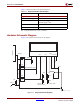
Display Hardware Design
The FPGA (I/O functioning at 2.5V) is connected to the graphic LCD panel through a set of
voltage-level converting devices. These switches translate the 2.5 I/O voltage to a 3.3V
voltage for the LCD panel.
A graphics-based LCD panel from DisplayTech (64128EFCBC-XLP) is used on the Virtex-5
FPGA ML561 Development Board. The control for this LCD panel is based on the KS0713
controller from Samsung. The KS0713 is a 65-column, 132-segment driver-controller device
for graphic dot matrix LCD systems. The chip accepts serial or parallel display data. The
8-bit parallel interface is compatible with most LCD panel manufacturers. The serial
connection mode is write only.
Extra features added to the interface in addition to the normal parallel signals are:
• Intel or Motorola compatible interface
• External reset of the chip
• External chip select
The interface also contains the following built-in options for the display and controller:
• On-chip oscillator circuitry
• On-chip voltage converter (x2, x3, x4, and x5)
• A 64-step electronic contrast control function