MicroBlaze Processor Reference Guide Embedded Development Kit EDK 8.2i UG081 (v6.
© 2006 Xilinx, Inc. All Rights Reserved. XILINX, the Xilinx logo, and other designated brands included herein are trademarks of Xilinx, Inc. All other trademarks are the property of their respective owners. NOTICE OF DISCLAIMER: Xilinx is providing this design, code, or information "as is." By providing the design, code, or information as one possible implementation of this feature, application, or standard, Xilinx makes no representation that this implementation is free from any claims of infringement.
MicroBlaze Processor Reference Guide UG081 (v6.0) June 1, 2006 The following table shows the revision history for this document. Date Version 10/01/02 1.0 Xilinx EDK 3.1 release 03/11/03 2.0 Xilinx EDK 3.2 release 09/24/03 3.0 Xilinx EDK 6.1 release 02/20/04 3.1 Xilinx EDK 6.2 release 08/24/04 4.0 Xilinx EDK 6.3 release 09/21/04 4.1 Minor corrections for EDK 6.3 SP1 release 11/18/04 4.2 Minor corrections for EDK 6.3 SP2 release 01/20/05 5.0 Xilinx EDK 7.1 release 04/02/05 5.
MicroBlaze Processor Reference Guide www.xilinx.com 1-800-255-7778 UG081 (v6.
Preface: About This Guide Manual Contents . . . . . . . . . . . . . . . . . . . . . . . . . . . . . . . . . . . . . . . . . . . . . . . . . . . . . . . . . . . . . 7 Additional Resources . . . . . . . . . . . . . . . . . . . . . . . . . . . . . . . . . . . . . . . . . . . . . . . . . . . . . . . . 7 Conventions . . . . . . . . . . . . . . . . . . . . . . . . . . . . . . . . . . . . . . . . . . . . . . . . . . . . . . . . . . . . . . . . . 8 Typographical . . . . . . . . . . . . . . . . . . . . . . . . . . .
Features . . . . . . . . . . . . . . . . . . . . . . . . . . . . . . . . . . . . . . . . . . . . . . . . . . . . . . . . . . . . . . . . . MicroBlaze I/O Overview . . . . . . . . . . . . . . . . . . . . . . . . . . . . . . . . . . . . . . . . . . . . . . . . . . . On-Chip Peripheral Bus (OPB) Interface Description . . . . . . . . . . . . . . . . . . . . . . . . Local Memory Bus (LMB) Interface Description . . . . . . . . . . . . . . . . . . . . . . . . . . . . . LMB Signal Interface . . . . . . . . . . . .
R Preface About This Guide Welcome to the MicroBlaze Processor Reference Guide. This document provides information about the 32-bit soft processor MicroBlaze, which is part of the Embedded Processor Development Kit (EDK). The document is intended as a guide to the MicroBlaze hardware architecture.
R Preface: About This Guide Resource Description/URL Problem Solvers Interactive tools that allow you to troubleshoot your design issues http://support.xilinx.com/support/troubleshoot/psolvers.htm Tech Tips Latest news, design tips, and patch information for the Xilinx design environment http://www.support.xilinx.com/xlnx/xil_tt_home.jsp GNU Manuals The entire set of GNU manuals http://www.gnu.org/manual Conventions This document uses the following conventions.
R Conventions Convention Meaning or Use Example Vertical ellipsis . . . Repetitive material that has been omitted IOB #1: Name = QOUT’ IOB #2: Name = CLKIN’ . . . Horizontal ellipsis . . . Repetitive material that has been omitted allow block block_name loc1 loc2 ...
R 10 Preface: About This Guide www.xilinx.com 1-800-255-7778 MicroBlaze Processor Reference Guide UG081 (v6.
R Chapter 1 MicroBlaze Architecture Overview The MicroBlaze embedded processor soft core is a reduced instruction set computer (RISC) optimized for implementation in Xilinx field programmable gate arrays (FPGAs). Figure 1-1 shows a functional block diagram of the MicroBlaze core.
R Chapter 1: MicroBlaze Architecture In addition to these fixed features the MicroBlaze processor is parametrized to allow selective enabling of additional functionality. Older (deprecated) versions of MicroBlaze support a subset of the optional features described in this manual. Only the latest (active) version of MicroBlaze (v5.00a) supports all options. Xilinx recommends that all new designs use the latest active version of the MicroBlaze processor.
R Data Types and Endianness Data Types and Endianness MicroBlaze uses Big-Endian, bit-reversed format to represent data. The hardware supported data types for MicroBlaze are word, half word, and byte. The bit and byte organization for each type is shown in the following tables.
R Chapter 1: MicroBlaze Architecture Table 1-5: Instruction Set Nomenclature Symbol Description Ra R0 - R31, General Purpose Register, source operand a Rb R0 - R31, General Purpose Register, source operand b Rd R0 - R31, General Purpose Register, destination operand SPR[x] Special Purpose Register number x MSR Machine Status Register = SPR[1] ESR Exception Status Register = SPR[5] EAR Exception Address Register = SPR[3] FSR Floating Point Unit Status Register = SPR[7] PVRx Processor Ver
R Instructions Table 1-5: Instruction Set Nomenclature Symbol Description << x Bit shift left x bits and Logic AND or Logic OR xor Logic exclusive OR op1 if cond else op2 Perform op1 if condition cond is true, else perform op2 & Concatenate. E.g. “0000100 & Imm7” is the concatenation of the fixed field “0000100” and a 7 bit immediate value. signed Operation performed on signed integer data type.
R Table 1-6: Chapter 1: MicroBlaze Architecture MicroBlaze Instruction Set Summary (Continued) Type A 0-5 6-10 11-15 16-20 Type B 0-5 6-10 11-15 16-31 ADDIKC Rd,Ra,Imm 001110 Rd Ra Imm Rd := s(Imm) + Ra + C RSUBIKC Rd,Ra,Imm 001111 Rd Ra Imm Rd := s(Imm) + Ra + C MUL Rd,Ra,Rb 010000 Rd Ra Rb 00000000000 Rd := Ra * Rb BSRL Rd,Ra,Rb 010001 Rd Ra Rb 00000000000 Rd : = 0 & (Ra >> Rb) BSRA Rd,Ra,Rb 010001 Rd Ra Rb 01000000000 Rd := s(Ra >> Rb) BSLL Rd,Ra,Rb 010001
R Instructions Table 1-6: MicroBlaze Instruction Set Summary (Continued) Type A 0-5 6-10 11-15 16-20 Type B 0-5 6-10 11-15 16-31 PUT Ra,FSLx 011011 00000 Ra 1000000000000 & FSLx FSLx := Ra (blocking data write) NGET Rd,FSLx 011011 Rd 00000 0100000000000 & FSLx Rd := FSLx (non-blocking data read) MSR[FSL] := 1 if (FSLx_S_Control = 1) MSR[C] := not FSLx_S_Exists NPUT Ra,FSLx 011011 00000 Ra 1100000000000 & FSLx FSLx := Ra (non-blocking data write) MSR[C] := FSLx_M_Full CGET Rd,F
R Table 1-6: Chapter 1: MicroBlaze Architecture MicroBlaze Instruction Set Summary (Continued) Type A 0-5 6-10 11-15 16-20 Type B 0-5 6-10 11-15 16-31 100101 00000 Ra 11 & Sd MTS Sd,Ra 21-31 Semantics SPR[Sd] := Ra, where: • SPR[0x0001] is MSR • SPR[0x0007] is FSR MFS Rd,Sa 100101 Rd 00000 10 & Sa Rd := SPR[Sa], where: • • • • • • • SPR[0x0000] is PC SPR[0x0001] is MSR SPR[0x0003] is EAR SPR[0x0005] is ESR SPR[0x0007] is FSR SPR[0x000B] is BTR SPR[0x2000:0x200B] is PVR[0] to PVR[11
R Instructions Table 1-6: MicroBlaze Instruction Set Summary (Continued) Type A 0-5 6-10 11-15 16-20 Type B 0-5 6-10 11-15 BGTD Ra,Rb 100111 10100 Ra Rb 00000000000 PC := PC + Rb if Ra > 0 BGED Ra,Rb 100111 10101 Ra Rb 00000000000 PC := PC + Rb if Ra >= 0 ORI Rd,Ra,Imm 101000 Rd Ra Imm Rd := Ra or s(Imm) ANDI Rd,Ra,Imm 101001 Rd Ra Imm Rd := Ra and s(Imm) XORI Rd,Ra,Imm 101010 Rd Ra Imm Rd := Ra xor s(Imm) ANDNI Rd,Ra,Imm 101011 Rd Ra Imm Rd := Ra and s(Imm)
R Chapter 1: MicroBlaze Architecture Table 1-6: MicroBlaze Instruction Set Summary (Continued) Type A 0-5 6-10 11-15 16-20 21-31 Type B 0-5 6-10 11-15 16-31 BLEID Ra,Imm 101111 10011 Ra Imm PC := PC + s(Imm) if Ra <= 0 BGTID Ra,Imm 101111 10100 Ra Imm PC := PC + s(Imm) if Ra > 0 BGEID Ra,Imm 101111 10101 Ra Imm PC := PC + s(Imm) if Ra >= 0 LBU Rd,Ra,Rb 110000 Rd Ra Rb 00000000000 Addr := Ra + Rb Rd[0:23] := 0 Rd[24:31] := *Addr[0:7] LHU Rd,Ra,Rb 110001 Rd Ra Rb 0000
R Registers General Purpose Registers The thirty-two 32-bit General Purpose Registers are numbered R0 through R31. The register file is reset on bit stream download (reset value is 0x00000000). Note: The register file is not reset by the external reset inputs: reset and debug_rst. 0 31 ↑ R0-R31 Figure 1-2: R0-R31 Table 1-7: General Purpose Registers (R0-R31) Bits Name Description Reset Value 0x00000000 0:31 R0 R0 is defined to always have the value of zero. Anything written to R0 is discarded.
R Chapter 1: MicroBlaze Architecture 0 31 ↑ PC Figure 1-3: PC Table 1-8: Program Counter (PC) Bits 0:31 Name PC Description Reset Value 0x00000000 Program Counter Address of executing instruction, i.e. “mfs r2 0” will store the address of the mfs instruction itself in R2 Machine Status Register (MSR) The Machine Status Register contains control and status bits for the processor. It can be read with an MFS instruction. When reading the MSR, bit 29 is replicated in bit 0 as the carry copy.
R Registers Table 1-9: Machine Status Register (MSR) (Continued) Bits 22 Name EIP Description Exception In Progress Reset Value 0 0 No hardware exception in progress 1 Hardware exception in progress Read/Write 23 EE Exception Enable 0 0 Hardware exceptions disabled 1 Hardware exceptions enabled Read/Write 24 DCE Data Cache Enable 0 0 Data Cache is Disabled 1 Data Cache is Enabled Read/Write 25 DZ Division by Zero1 0 0 No division by zero has occurred 1 Division by zero has occurred Read/Wr
R Chapter 1: MicroBlaze Architecture Table 1-9: Machine Status Register (MSR) (Continued) Bits 29 Name C Description Reset Value 0 Arithmetic Carry 0 No Carry (Borrow) 1 Carry (No Borrow) Read/Write 30 IE 0 Interrupt Enable 0 Interrupts disabled 1 Interrupts enabled Read/Write 31 Buslock Enable2 BE 0 0 Buslock disabled on data-side OPB 1 Buslock enabled on data-side OPB Buslock Enable does not affect operation of IXCL, DXCL, ILMB, DLMB, or IOPB. Read/Write 1.
R Registers Exception Status Register (ESR) The Exception Status Register contains status bits for the processor. When read with the MFS instruction the ESR is specified by setting Sa = 0x0005. 19 20 ↑ RESERVED Figure 1-6: 26 27 31 ↑ ↑ ↑ DS ESS EC ESR Table 1-11: Exception Status Register (ESR) Bits Name 0:18 Reserved 19 DS Description Exception in delay slot.
R Chapter 1: MicroBlaze Architecture Table 1-12: Exception Specific Status (ESS) Exception Cause Bits Unaligned 20 Data Access Name Description W Word Access Exception Reset Value 0 0 unaligned halfword access 1 unaligned word access 21 S Store Access Exception 0 0 unaligned load access 1 unaligned store access 22:26 Rx Source/Destination Register 0 General purpose register used as source (Store) or destination (Load) in unaligned access Illegal Instruction 20:26 Reserved 0 Instructi
R Registers Table 1-13: Branch Target Register (BTR) Bits 0:31 Name Description BTR Branch target address used by handler when returning from an exception caused by an instruction in a delay slot Reset Value 0x00000000 Read-only Floating Point Status Register (FSR) The Floating Point Status Register contains status bits for the floating point unit. It can be read with an MFS, and written with an MTS instruction. When read or written, the register is specified by setting Sa = 0x0007.
R Chapter 1: MicroBlaze Architecture Table 1-15: Processor Version Register 0 (PVR0) Bits Name Description Value 0 CFG PVR implementation: 0=basic, 1=full Based on C_PVR 1 BS Use barrel shifter C_USE_BARREL 2 DIV Use divider C_USE_DIV 3 MUL Use hardware multiplier C_USE_HW_MUL 4 FPU Use FPU C_USE_FPU 5 EXC Use any type of exceptions Based on C_*_EXCEPTION 6 ICU Use instruction cache C_USE_ICACHE 7 DCU Use data cache C_USE_DCACHE 8:15 Reserved 16:23 MBV 0 MicroBlaze
R Registers Table 1-17: Processor Version Register 2 (PVR2) (Continued) Bits Table 1-18: Name Description Value 25 OP0EXEC Generate exception for 0x0 illegal opcode C_OPCODE_0x0_ILLEGAL 26 UNEXEC Generate exception for unaligned data access C_UNALIGNED_EXCEPTION 27 OPEXEC Generate exception for any illegal opcode C_ILL_OPCODE_EXCEPTION 28 IOPBEXEC Generate exception for IOPB error C_IOPB_BUS_EXCEPTION 29 DOPBEXEC Generate exception for DOPB error C_DOPB_BUS_EXCEPTION 30 DIVEXEC
R Chapter 1: MicroBlaze Architecture Table 1-19: Processor Version Register 4 (PVR4) (Continued) Bits Name Description Value 8:10 ICLL Instruction cache line length 2^n C_ICACHE_LINE_LEN 11:15 ICBS Instruction cache byte size 2^n C_CACHE_BYTE_SIZE 16:31 Reserved 0 Table 1-20: Processor Version Register 5 (PVR5) Bits Name Description Value 0 DCU Use data cache C_USE_DCACHE 1:5 DCTS Data cache tag size C_DCACHE_ADDR_TAG 6 Reserved 7 DCW Allow data cache write C_ALLOW_DCACHE_W
R Pipeline Architecture Table 1-25: Processor Version Register 10 (PVR10) Bits 0:7 Name Description ARCH Value Target architecture: Defined by option C_TARGET 0x4 = Virtex2 0x5 = Virtex2Pro 0x6 = Spartan3 0x7 = Virtex4 0x8 = Virtex5 0x9 = Spartan3E 8:31 Reserved 0 Table 1-26: Processor Version Register 11 (PVR11) Bits Name Description Value 0:20 DO Reset value for MSR 0 21:31 RSTMSR Reset value for MSR C_RESET_MSR Pipeline Architecture MicroBlaze instruction execution is pipelined.
R Chapter 1: MicroBlaze Architecture Branches Normally the instructions in the fetch and decode stages (as well as prefetch buffer) are flushed when executing a taken branch. The fetch pipeline stage is then reloaded with a new instruction from the calculated branch address. A taken branch in MicroBlaze takes three clock cycles to execute, two of which are required for refilling the pipeline. To reduce this latency overhead, MicroBlaze supports branches with delay slots.
R Reset, Interrupts, Exceptions, and Break Reset, Interrupts, Exceptions, and Break MicroBlaze supports reset, interrupt, user exception, break, and hardware exceptions. The following section describes the execution flow associated with each of these events. The relative priority starting with the highest is: 1. Reset 2. Hardware Exception 3. Non-maskable Break 4. Break 5. Interrupt 6.
R Chapter 1: MicroBlaze Architecture Reset When a Reset or Debug_Rst (1) occurs, MicroBlaze will flush the pipeline and start fetching instructions from the reset vector (address 0x0). Both external reset signals are active high, and should be asserted for a minimum of 16 cycles.
R Reset, Interrupts, Exceptions, and Break • Unaligned Exception The unaligned exception is caused by a word access where the address to the data bus has bits 30 or 31 set, or a half-word access with bit 31 set. • Divide by Zero Exception The divide-by-zero exception is causes by an integer division (idiv or idivu) where the divisor is zero.
R Chapter 1: MicroBlaze Architecture Software Breaks To perform a software break, use the brk and brki instructions. Refer to Chapter 4, “MicroBlaze Instruction Set Architecture” for detailed information on software breaks. Latency The time it will take MicroBlaze to enter a break service routine from the time the break occurs, depends on the instruction currently in the execution stage and the latency to the memory storing the break vector.
R Instruction Cache PC ← 0x00000008 Instruction Cache Overview MicroBlaze may be used with an optional instruction cache for improved performance when executing code that resides outside the LMB address range.
R Chapter 1: MicroBlaze Architecture For example: in a MicroBlaze configured with C_ICACHE_BASEADDR= 0x00300000, C_ICACHE_HIGHADDR=0x0030ffff, C_CACHE_BYTE_SIZE=4096, and C_ICACHE_LINELEN=8; the cacheable memory of 64 kB uses 16 bits of byte address, and the 4 kB cache uses 12 bits of byte address, thus the required address tag width is: 16-12=4 bits.
R Data Cache • Cache on and off controlled using a bit in the MSR • Optional WDC instruction to invalidate data cache lines General Data Cache Functionality When the data cache is used, the memory address space in split into two segments: a cacheable segment and a non-cacheable segment. The cacheable area is determined by two parameters: C_DCACHE_BASEADDR and C_DCACHE_HIGHADDR. All addresses within this range correspond to the cacheable address space. All other addresses are noncacheable.
R Chapter 1: MicroBlaze Architecture A load from an address within the cacheable range will, provided that the cache is enabled, trigger a check to determine if the requested data is currently cached. If it is (i.e. on a cachehit) the requested data is retrieved from the cache. If not (i.e. on a cache-miss) the address is requested over data CacheLink (DXCL), and the processor pipeline will stall until the cache line associated to the requested address is returned from the external memory controller.
R Floating Point Unit (FPU) Format An IEEE 754 single precision floating point number is composed of the following three fields: 1. 1-bit sign 2. 8-bit biased exponent 3. 23-bit fraction (a.k.a. mantissa or significand) The fields are stored in a 32 bit word as defined in Figure 1-11: 0 ↑ sign 1 9 31 ↑ ↑ exponent fraction Figure 1-11: IEEE 754 Single Precision format The value of a floating point number v in MicroBlaze has the following interpretation: 1.
R Chapter 1: MicroBlaze Architecture Comparison The FPU implements the following floating point comparisons: • compare less-than, fcmp.lt • compare equal, fcmp.eq • compare less-or-equal, fcmp.le • compare greater-than, fcmp.gt • compare not-equal, fcmp.ne • compare greater-or-equal, fcmp.ge • compare unordered, fcmp.un (used for NaN) Exceptions The floating point unit uses the regular hardware exception mechanism in MicroBlaze.
R Debug and Trace Example code: FSLx // Configure fx Custom HW Accelerator cput Rc,RFSLx MicroBlaze // Store operands put Ra, RFSLx // op 1 put Rb, RFSLx // op 2 Register File // Load result Op1Reg Op2Reg ConfigReg fx ResultReg get Rt, RFSLx FSLx Figure 1-12: FSL used with HW accelerated function fx This method is similar to extending the ISA with custom instructions, but has the benefit of not making the overall speed of the processor pipeline dependent on the custom function.
R 44 Chapter 1: MicroBlaze Architecture www.xilinx.com 1-800-255-7778 MicroBlaze Processor Reference Guide UG081 (v6.
R Chapter 2 MicroBlaze Signal Interface Description Overview The MicroBlaze core is organized as a Harvard architecture with separate bus interface units for data accesses and instruction accesses. The following three memory interfaces are supported: Local Memory Bus (LMB), IBM’s On-chip Peripheral Bus (OPB), and Xilinx CacheLink (XCL). The LMB provides single-cycle access to on-chip dual-port block RAM. The OPB interface provides a connection to both on-chip and off-chip peripherals and memory.
R Chapter 2: MicroBlaze Signal Interface Description Instruction-side bus interface Data-side bus interface ALU IXCL_S Program Counter Special Purpose Registers Shift Barrel Shift D-Cache I-Cache IXCL_M DXCL_M DXCL_S Multiplier Divider IOPB ILMB Bus IF FPU Bus IF Instruction Buffer DOPB DLMB Instruction Decode MFSL 0..7 Register File 32 X 32b SFSL 0..
R MicroBlaze I/O Overview Table 2-1: Summary of MicroBlaze Core I/O (Continued) Signal Interface I/O IM_BE[0:3] IOPB O Instruction interface OPB byte enables IM_busLock IOPB O Instruction interface OPB bus lock IM_DBus[0:31] IOPB O Instruction interface OPB write data bus (always 0x00000000) IM_request IOPB O Instruction interface OPB bus request IM_RNW IOPB O Instruction interface OPB read, not write (tied to IM_select) IM_select IOPB O Instruction interface OPB select IM_seqAd
R Chapter 2: MicroBlaze Signal Interface Description Table 2-1: Summary of MicroBlaze Core I/O (Continued) Signal Interface I/O Description ICache_FSL_out... IXCL_M IO Instruction side CacheLink FSL master interface DCache_FSL_in... DXCL_S IO Data side CacheLink FSL slave interface DCache_FSL_out... DXCL_M IO Data side CacheLink FSL master interface Interrupt Core I Interrupt Reset Core I Core reset, active high.
R Local Memory Bus (LMB) Interface Description Local Memory Bus (LMB) Interface Description The LMB is a synchronous bus used primarily to access on-chip block RAM. It uses a minimum number of control signals and a simple protocol to ensure that local block RAM are accessed in a single clock cycle. LMB signals and definitions are shown in the following table. All LMB signals are active high.
R Chapter 2: MicroBlaze Signal Interface Description Table 2-3: Valid Values for Byte_Enable[0:3] Byte Lanes Used Byte_Enable[0:3] Data[0:7] 1000 x Data[8:15] 0011 1100 x x 1111 x x Data[16:23] Data[24:31] x x x x Data_Write[0:31] The write data bus is an output from the core and contains the data that is written to memory. It becomes valid when AS is high and goes invalid in the clock cycle after Ready is sampled high. Only the byte lanes specified by Byte_Enable[0:3] contain valid data.
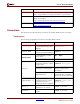
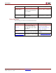
R Local Memory Bus (LMB) Interface Description LMB Transactions The following diagrams provide examples of LMB bus operations. Generic Write Operation Clk Addr A0 Byte_Enable 1111 Data_Write D0 AS Read_Strobe Write_Strobe Data_Read Ready Figure 2-2: LMB Generic Write Operation Generic Read Operation Clk Addr A0 Byte_Enable 1111 Data_Write AS Read_Strobe Write_Strobe Data_Read D0 Ready Figure 2-3: MicroBlaze Processor Reference Guide UG081 (v6.
R Chapter 2: MicroBlaze Signal Interface Description Back-to-Back Write Operation Clk Addr A0 A1 A2 Byte_Enable BE0 BE1 BE2 Data_Write AS Read_Strobe Write_Strobe Data_Read Ready Figure 2-4: LMB Back-to-Back Write Operation Single Cycle Back-to-Back Read Operation Clk Addr A0 A1 A2 Byte_Enable BE0 BE1 BE2 D0 D1 Data_Write AS Read_Strobe Write_Strobe Data_Read D2 Ready Figure 2-5: LMB Single Cycle Back-to-Back Read Operation Back-to-Back Mixed Read/Write Operation Clk Addr A0 A1
R Local Memory Bus (LMB) Interface Description Read and Write Data Steering The MicroBlaze data-side bus interface performs the read steering and write steering required to support the following transfers: • byte, halfword, and word transfers to word devices • byte and halfword transfers to halfword devices • byte transfers to byte devices MicroBlaze does not support transfers that are larger than the addressed device.
R Chapter 2: MicroBlaze Signal Interface Description Fast Simplex Link (FSL) Interface Description The Fast Simplex Link bus provides a point-to-point communication channel between an output FIFO and an input FIFO. For details on the generic FSL protocol please refer to the “Fast Simplex Link (FSL) bus” data sheet (DS449). Master FSL Signal Interface MicroBlaze may contain up to 8 master FSL interfaces. The master signals are depicted in Table 2-6.
R Xilinx CacheLink (XCL) Interface Description FSL Transactions FSL BUS Write Operation A write to the FSL bus is performed by MicroBlaze using one of the flavors of the put instruction. A write operations transfers the register contents to an output FSL bus. The transfer is completed in a single clock cycle for blocking mode writes to the FSL (put and cput instructions) as long as the FSL FIFO does not become full. If the FSL FIFO is full, the processor stalls until the FSL full flag is lowered.
R Chapter 2: MicroBlaze Signal Interface Description The MicroBlaze CacheLink interface can also connect to an Fast Simplex Link (FSL) interfaced memory controller via explicitly instantiated FSL master/slave pair, however this topology is considered deprecated and is not recommended for new designs. The interface is only available on MicroBlaze when caches are enabled. It is legal to use a CacheLink cache on the instruction side or the data side without caching the other.
R Xilinx CacheLink (XCL) Interface Description Table 2-8: MicroBlaze Cache Link signals Signal Name Description VHDL Type Direction DCACHE_FSL_IN_Read Read signal to D-side return read data FSL std_logic output DCACHE_FSL_IN_Data Read data from D-side return read data FSL std_logic_vector (0 to 31) input DCACHE_FSL_IN_Control FSL control bit from Dside return read data FSL std_logic input DCACHE_FSL_IN_Exists More read data exists in D-side return FSL std_logic input DCACHE_FSL_OUT_Clk
R Chapter 2: MicroBlaze Signal Interface Description The CacheLink solution uses one incoming (slave) and one outgoing (master) FSL per cache controller. The outgoing FSL is used to send access requests, while the incoming FSL is used for receiving the requested cache lines. CacheLink also uses a specific encoding of the transaction information over the FSL data and control signals. The cache lines used for reads in the CacheLink protocol are 4 words long.
R Debug Interface Description 0b01=byte1 or halfword0, 0x10=byte2, and 0x11=byte3 or halfword1. The selection of half-word or byte access is based on the control bit for the data word in step 4. 3. If DCACHE_FSL_OUT_Full = 1 then stall until it goes low 4. Write the data to be stored to DCACHE_FSL_OUT_Data. For byte and halfword accesses the data is mirrored accordingly onto byte-lanes. The control bit should be low (DCACHE_FSL_OUT_Control = 0) for a word or halfword access, and high for a byte access.
R Chapter 2: MicroBlaze Signal Interface Description Table 2-10: MicroBlaze Trace signals Signal Name 60 Description VHDL Type Direction Trace_Reg_Write1 Instruction writes to the register file std_logic output Trace_Reg_Addr1 Destination register address std_logic_vector (0 to 4) output Trace_MSR_Reg1 Machine status register std_logic_vector (0 to10) output Trace_New_Reg_Value1 Destination register update value std_logic_vector (0 to 31) output Trace_Exception_Taken1 Instruction res
R MicroBlaze Core Configurability Table 2-10: MicroBlaze Trace signals Signal Name Description VHDL Type Direction Trace_OF_PipeRun Pipeline advance for Decode stage std_logic output Trace_EX_PipeRun Pipeline advance for Execution stage std_logic output Trace_MEM_PipeRun Pipeline advance for Memory stage std_logic output 1.
R Chapter 2: MicroBlaze Signal Interface Description Parameters valid for MicroBlaze v5.00a are listed in Table 2-12. Note that not all of these are recognized by older versions of MicroBlaze, however the configurability is fully backward compatibility.
R MicroBlaze Core Configurability Table 2-12: MPD Parameters Parameter Name Allowable Values Feature/Description Default EDK Tool Value Assigned VHDL Type C_USE_FPU Include hardware floating point unit (Virtex2 and later) 0, 1 0 integer C_USE_MSR_INSTR Enable use of instructions: MSRSET and MSRCLR 1 1 integer C_USE_PCMP_INSTR Enable use of instructions: PCMPBF, PCMPEQ, and PCMPNE 1 1 integer C_UNALIGNED_EXCEPTION Enable exception handling for unaligned data accesses 0, 1 0 intege
R Table 2-12: Chapter 2: MicroBlaze Signal Interface Description MPD Parameters Parameter Name Allowable Values Feature/Description Default EDK Tool Value Assigned VHDL Type C_ICACHE_HIGHADDR Instruction cache high address 0x00000000 0xFFFFFFFF 0x3FFF FFFF std_logi c_vector C_USE_ICACHE Instruction cache 0, 1 0 integer C_ALLOW_ICACHE_WR Instruction cache write enable 0, 1 1 integer C_ICACHE_LINELEN Instruction cache line length 4, 8 4 integer C_ADDR_TAG_BITS Instruction cache a
R Chapter 3 MicroBlaze Application Binary Interface Scope This document describes MicroBlaze Application Binary Interface (ABI), which is important for developing software in assembly language for the soft processor. The MicroBlaze GNU compiler follows the conventions described in this document. Hence any code written by assembly programmers should also follow the same conventions to be compatible with the compiler generated code. Interrupt and Exception handling is also explained briefly in the document.
R Chapter 3: MicroBlaze Application Binary Interface Register Usage Conventions The register usage convention for MicroBlaze is given in Table 3-2.
R Stack Convention • • Certain registers are used as dedicated registers and programmers are not expected to use them for any other purpose. ♦ Registers R14 through R17 are used for storing the return address from interrupts, sub-routines, traps, and exceptions in that order. Sub-routines are called using the branch and link instruction, which saves the current Program Counter (PC) onto register R15.
R Chapter 3: MicroBlaze Application Binary Interface Figure 3-1: Stack Convention High Address Function Parameters for called sub-routine (Arg n ..Arg1) (Optional: Maximum number of arguments required for any called procedure from the current procedure.) Old Stack Pointer Link Register (R15) Callee Saved Register (R31....
R Memory Model Figure 3-2: Stack Frame Calling Convention The caller function passes parameters to the callee function using either the registers (R5 through R10) or on its own stack frame. The callee uses the caller’s stack area to store the parameters passed to the callee. Refer to Figure 3-2. The parameters for Func 2 are stored either in the registers R5 through R10 or on the stack frame allocated for Func 1.
R Chapter 3: MicroBlaze Application Binary Interface Interrupt and Exception Handling MicroBlaze assumes certain address locations for handling interrupts and exceptions as indicated in Table 3-3. At these locations, code is written to jump to the appropriate handlers.
R Chapter 4 MicroBlaze Instruction Set Architecture Summary This chapter provides a detailed guide to the Instruction Set Architecture of MicroBlaze™. Notation The symbols used throughout this document are defined in Table 4-1.
R Chapter 4: MicroBlaze Instruction Set Architecture Table 4-1: Symbol notation Symbol Meaning Memory location at address x Mem(x) FSL interface x FSLx LSW(x) Least Significant Word of x isDnz(x) Floating point: true if x is denormalized Floating point: true if x is +∞ or -∞ isInfinite(x) isPosInfinite(x) Floating point: true if x is +∞ isNegInfinite(x) Floating point: true if x -∞ isNaN(x) Floating point: true if x is a quiet or signalling NaN isZero(x) Floating point: true if x is +0 or -
R Instructions add 0 Arithmetic Add 0 add rD, rA, rB Add addc rD, rA, rB Add with Carry addk rD, rA, rB Add and Keep Carry addkc rD, rA, rB Add with Carry and Keep Carry 0 K C 0 rD 0 6 rA 11 rB 16 0 0 0 0 0 0 0 0 0 21 0 0 31 Description The sum of the contents of registers rA and rB, is placed into register rD. Bit 3 of the instruction (labeled as K in the figure) is set to a one for the mnemonic addk.
R Chapter 4: MicroBlaze Instruction Set Architecture addi 0 0 Arithmetic Add Immediate 0 addi rD, rA, IMM Add Immediate addic rD, rA, IMM Add Immediate with Carry addik rD, rA, IMM Add Immediate and Keep Carry addikc rD, rA, IMM Add Immediate with Carry and Keep Carry 1 K C 0 rD 6 rA 11 IMM 16 31 Description The sum of the contents of registers rA and the value in the IMM field, sign-extended to 32 bits, is placed into register rD.
R Instructions and Logical AND and 1 0 0 0 0 0 1 rD, rA, rB rD 6 rA 11 rB 16 0 21 0 0 0 0 0 0 0 0 0 0 31 Description The contents of register rA are ANDed with the contents of register rB; the result is placed into register rD. Pseudocode (rD) ← (rA) ∧ (rB) Registers Altered • rD Latency 1 cycle MicroBlaze Processor Reference Guide UG081 (v6.0) June 1, 2006 www.xilinx.
R Chapter 4: MicroBlaze Instruction Set Architecture andi Logial AND with Immediate andi 1 0 1 0 0 1 rD, rA, IMM rD 0 6 rA 11 IMM 16 31 Description The contents of register rA are ANDed with the value of the IMM field, sign-extended to 32 bits; the result is placed into register rD.
R Instructions andn Logical AND NOT andn 1 0 0 0 0 1 1 rD, rA, rB rD 6 rA 11 rB 16 0 21 0 0 0 0 0 0 0 0 0 0 31 Description The contents of register rA are ANDed with the logical complement of the contents of register rB; the result is placed into register rD. Pseudocode (rD) ← (rA) ∧ (rB) Registers Altered • rD Latency 1 cycle MicroBlaze Processor Reference Guide UG081 (v6.0) June 1, 2006 www.xilinx.
R Chapter 4: MicroBlaze Instruction Set Architecture andni Logical AND NOT with Immediate andni 1 0 1 0 1 1 rD, rA, IMM rD 0 6 rA 11 IMM 16 31 Description The IMM field is sign-extended to 32 bits. The contents of register rA are ANDed with the logical complement of the extended IMM field; the result is placed into register rD.
R Instructions beq 1 Branch if Equal 0 0 1 1 beq rA, rB Branch if Equal beqd rA, rB Branch if Equal with Delay 1 D 0 0 0 0 0 6 rA 11 rB 16 0 0 0 0 0 21 0 0 0 0 0 0 31 Description Branch if rA is equal to 0, to the instruction located in the offset value of rB. The target of the branch will be the instruction at address PC + rB. The mnemonic beqd will set the D bit. The D bit determines whether there is a branch delay slot or not.
R Chapter 4: MicroBlaze Instruction Set Architecture beqi 1 Branch Immediate if Equal 0 1 1 1 beqi rA, IMM Branch Immediate if Equal beqid rA, IMM Branch Immediate if Equal with Delay 1 D 0 0 0 0 0 6 rA 11 IMM 16 31 Description Branch if rA is equal to 0, to the instruction located in the offset value of IMM. The target of the branch will be the instruction at address PC + IMM. The mnemonic beqid will set the D bit. The D bit determines whether there is a branch delay slot or not.
R Instructions bge 1 Branch if Greater or Equal 0 0 1 1 bge rA, rB Branch if Greater or Equal bged rA, rB Branch if Greater or Equal with Delay 1 D 0 0 1 0 1 6 rA 11 rB 16 0 0 0 0 0 21 0 0 0 0 0 0 31 Description Branch if rA is greater or equal to 0, to the instruction located in the offset value of rB. The target of the branch will be the instruction at address PC + rB. The mnemonic bged will set the D bit. The D bit determines whether there is a branch delay slot or not.
R Chapter 4: MicroBlaze Instruction Set Architecture bgei 1 Branch Immediate if Greater or Equal 0 1 1 1 bgei rA, IMM Branch Immediate if Greater or Equal bgeid rA, IMM Branch Immediate if Greater or Equal with Delay 1 D 0 0 1 0 1 6 rA 11 IMM 16 31 Description Branch if rA is greater or equal to 0, to the instruction located in the offset value of IMM. The target of the branch will be the instruction at address PC + IMM. The mnemonic bgeid will set the D bit.
R Instructions bgt 1 Branch if Greater Than 0 0 1 1 bgt rA, rB Branch if Greater Than bgtd rA, rB Branch if Greater Than with Delay 1 D 0 0 1 0 0 6 rA 11 rB 16 0 0 0 0 0 21 0 0 0 0 0 0 31 Description Branch if rA is greater than 0, to the instruction located in the offset value of rB. The target of the branch will be the instruction at address PC + rB. The mnemonic bgtd will set the D bit. The D bit determines whether there is a branch delay slot or not.
R Chapter 4: MicroBlaze Instruction Set Architecture bgti 1 Branch Immediate if Greater Than 0 1 1 1 bgti rA, IMM Branch Immediate if Greater Than bgtid rA, IMM Branch Immediate if Greater Than with Delay 1 D 0 0 1 0 0 6 rA 11 IMM 16 31 Description Branch if rA is greater than 0, to the instruction located in the offset value of IMM. The target of the branch will be the instruction at address PC + IMM. The mnemonic bgtid will set the D bit.
R Instructions ble 1 Branch if Less or Equal 0 0 1 1 ble rA, rB Branch if Less or Equal bled rA, rB Branch if Less or Equal with Delay 1 D 0 0 0 1 1 6 rA 11 rB 16 0 0 0 0 0 21 0 0 0 0 0 0 31 Description Branch if rA is less or equal to 0, to the instruction located in the offset value of rB. The target of the branch will be the instruction at address PC + rB. The mnemonic bled will set the D bit. The D bit determines whether there is a branch delay slot or not.
R Chapter 4: MicroBlaze Instruction Set Architecture blei 1 Branch Immediate if Less or Equal 0 1 1 1 blei rA, IMM Branch Immediate if Less or Equal bleid rA, IMM Branch Immediate if Less or Equal with Delay 1 D 0 0 0 1 1 6 rA 11 IMM 16 31 Description Branch if rA is less or equal to 0, to the instruction located in the offset value of IMM. The target of the branch will be the instruction at address PC + IMM. The mnemonic bleid will set the D bit.
R Instructions blt Branch if Less Than 1 0 0 1 1 blt rA, rB Branch if Less Than bltd rA, rB Branch if Less Than with Delay 1 D 0 0 0 1 0 6 rA 11 rB 16 0 0 0 0 0 21 0 0 0 0 0 0 31 Description Branch if rA is less than 0, to the instruction located in the offset value of rB. The target of the branch will be the instruction at address PC + rB. The mnemonic bltd will set the D bit. The D bit determines whether there is a branch delay slot or not.
R Chapter 4: MicroBlaze Instruction Set Architecture blti 1 Branch Immediate if Less Than 0 1 1 1 blti rA, IMM Branch Immediate if Less Than bltid rA, IMM Branch Immediate if Less Than with Delay 1 D 0 0 0 1 0 6 rA 11 IMM 16 31 Description Branch if rA is less than 0, to the instruction located in the offset value of IMM. The target of the branch will be the instruction at address PC + IMM. The mnemonic bltid will set the D bit.
R Instructions bne 1 Branch if Not Equal 0 0 1 1 bne rA, rB Branch if Not Equal bned rA, rB Branch if Not Equal with Delay 1 D 0 0 0 0 1 6 rA 11 rB 16 0 0 0 0 0 21 0 0 0 0 0 0 31 Description Branch if rA not equal to 0, to the instruction located in the offset value of rB. The target of the branch will be the instruction at address PC + rB. The mnemonic bned will set the D bit. The D bit determines whether there is a branch delay slot or not.
R Chapter 4: MicroBlaze Instruction Set Architecture bnei 1 Branch Immediate if Not Equal 0 1 1 1 bnei rA, IMM Branch Immediate if Not Equal bneid rA, IMM Branch Immediate if Not Equal with Delay 1 D 0 0 0 0 1 6 rA 11 IMM 16 31 Description Branch if rA not equal to 0, to the instruction located in the offset value of IMM. The target of the branch will be the instruction at address PC + IMM. The mnemonic bneid will set the D bit.
R Instructions br Unconditional Branch 1 0 0 0 1 1 br rB Branch bra rB Branch Absolute brd rB Branch with Delay brad rB Branch Absolute with Delay brld rD, rB Branch and Link with Delay brald rD, rB Branch Absolute and Link with Delay 0 rD 6 D A L 0 11 0 rB 16 0 0 0 0 0 0 0 0 0 0 21 0 31 Description Branch to the instruction located at address determined by rB. The mnemonics brld and brald will set the L bit. If the L bit is set, linking will be performed.
R Chapter 4: MicroBlaze Instruction Set Architecture Note The instructions brl and bral are not available. A delay slot must not be used by the following: IMM, branch, or break instructions. This also applies to instructions causing recoverable exceptions (e.g. unalignement), when hardware exceptions are enabled. Interrupts and external hardware breaks are deferred until after the delay slot branch has been completed. 92 www.xilinx.com 1-800-255-7778 MicroBlaze Processor Reference Guide UG081 (v6.
R Instructions bri 1 0 Unconditional Branch Immediate 0 1 1 1 bri IMM Branch Immediate brai IMM Branch Absolute Immediate brid IMM Branch Immediate with Delay braid IMM Branch Absolute Immediate with Delay brlid rD, IMM Branch and Link Immediate with Delay bralid rD, IMM Branch Absolute and Link Immediate with Delay 0 rD 6 D A L 0 11 0 IMM 16 31 Description Branch to the instruction located at address determined by IMM, sign-extended to 32 bits.
R Chapter 4: MicroBlaze Instruction Set Architecture Notes The instructions brli and brali are not available. By default, Type B Instructions will take the 16-bit IMM field value and sign extend it to 32 bits to use as the immediate operand. This behavior can be overridden by preceding the Type B instruction with an imm instruction. See the imm instruction for details on using 32-bit immediate values. A delay slot must not be used by the following: IMM, branch, or break instructions.
R Instructions brk Break brk 1 0 0 0 1 1 0 rD, rB rD 6 0 11 1 1 0 0 rB 16 0 21 0 0 0 0 0 0 0 0 0 0 31 Description Branch and link to the instruction located at address value in rB. The current value of PC will be stored in rD. The BIP flag in the MSR will be set. Pseudocode (rD) ← PC PC ← (rB) MSR[BIP] ← 1 Registers Altered • rD • PC • MSR[BIP] Latency 3 cycles MicroBlaze Processor Reference Guide UG081 (v6.0) June 1, 2006 www.xilinx.
R Chapter 4: MicroBlaze Instruction Set Architecture brki Break Immediate brki 1 0 1 1 1 0 rD, IMM rD 0 6 0 11 1 1 0 0 IMM 16 31 Description Branch and link to the instruction located at address value in IMM, sign-extended to 32 bits. The current value of PC will be stored in rD. The BIP flag in the MSR will be set.
R Instructions bs Barrel Shift 0 1 0 0 0 bsrl rD, rA, rB Barrel Shift Right Logical bsra rD, rA, rB Barrel Shift Right Arithmetical bsll rD, rA, rB Barrel Shift Left Logical 1 rD 0 6 rA 11 rB 16 S T 0 21 0 0 0 0 0 0 0 0 31 Description Shifts the contents of register rA by the amount specified in register rB and puts the result in register rD. The mnemonic bsll sets the S bit (Side bit). If the S bit is set, the barrel shift is done to the left.
R Chapter 4: MicroBlaze Instruction Set Architecture bsi 0 0 Barrel Shift Immediate 1 1 0 0 bsrli rD, rA, IMM Barrel Shift Right Logical Immediate bsrai rD, rA, IMM Barrel Shift Right Arithmetical Immediate bslli rD, rA, IMM Barrel Shift Left Logical Immediate 1 rD 6 rA 11 0 0 16 0 0 0 S T 21 0 0 0 0 IMM 27 31 Description Shifts the contents of register rA by the amount specified by IMM and puts the result in register rD. The mnemonic bsll sets the S bit (Side bit).
R Instructions cmp 0 0 Integer Compare 0 0 1 0 cmp rD, rA, rB compare rB with rA (signed) cmpu rD, rA, rB compare rB with rA (unsigned) 1 rD 6 rA 11 rB 16 0 21 0 0 0 0 0 0 0 0 U 1 31 Description The contents of register rA is subtracted from the contents of register rB and the result is placed into register rD. The MSB bit of rD is adjusted to shown true relation between rA and rB. If the U bit is set, rA and rB is considered unsigned values.
R Chapter 4: MicroBlaze Instruction Set Architecture fadd Floating Point Arithmetic Add rD, rA, rB fadd 0 1 0 1 1 0 rD 0 6 Add rA 11 rB 16 0 0 0 0 0 0 0 21 0 0 0 0 31 Description The floating point sum of registers rA and rB, is placed into register rD.
R Instructions frsub Reverse Floating Point Arithmetic Subtraction rD, rA, rB frsub 0 1 0 1 1 0 rD 0 6 Reverse subtract rA 11 rB 16 0 0 0 1 0 21 0 0 0 0 0 0 31 Description The floating point value in rA is subtracted from the floating point value in rB and the result is placed into register rD.
R Chapter 4: MicroBlaze Instruction Set Architecture fmul Floating Point Arithmetic Multiplication rD, rA, rB fmul 0 1 0 1 1 0 rD 0 6 Multiply rA 11 rB 16 0 0 21 1 0 0 0 0 0 0 0 0 31 Description The floating point value in rA is multiplied with the floating point value in rB and the result is placed into register rD.
R Instructions fdiv Floating Point Arithmetic Division rD, rA, rB fdiv 0 1 0 1 1 0 rD 0 6 Divide rA 11 rB 16 0 0 1 1 0 0 0 0 21 0 0 0 31 Description The floating point value in rB is divided by the floating point value in rA and the result is placed into register rD.
R Chapter 4: MicroBlaze Instruction Set Architecture fcmp 0 Floating Point Number Comparison 1 0 1 1 fcmp.un rD, rA, rB Unordered floating point comparison fcmp.lt rD, rA, rB Less-than floating point comparison fcmp.eq rD, rA, rB Equal floating point comparison fcmp.le rD, rA, rB Less-or-Equal floating point comparison fcmp.gt rD, rA, rB Greater-than floating point comparison fcmp.ne rD, rA, rB Not-Equal floating point comparison fcmp.
R Instructions Table 4-2: Floating Point Comparison Operation Comparison Type Description Operand Relationship OpSel 100 Greater-than (rB) > (rA) (rD) ← 1 (rB) < (rA) (rD) ← 0 (rB) = (rA) (rD) ← 0 isNaN(rA) or isNaN(rB) (rD) ← 0 FSR[IO] ← 1 ESR[EC] ← 00110 Not-equal 101 (rD) ← 1 (rD) ← 1 (rD) ← 0 (rD) ← 1 Greater-or-equal 110 (rD) ← 1 (rD) ← 0 (rD) ← 1 (rD) ← 0 FSR[IO] ← 1 ESR[EC] ← 00110 Registers Altered • • • rD, unless an FP exception is generated, in which case the register is
R Chapter 4: MicroBlaze Instruction Set Architecture get 0 get from fsl interface 1 1 0 1 get rD, FSLx get data from FSL x (blocking) nget rD, FSLx get data from FSL x (non-blocking) cget rD, FSLx get control from FSL x (blocking) ncget rD, FSLx get control from FSL x (non-blocking) 1 rD 0 6 0 0 11 0 0 0 0 n c 0 0 16 0 0 0 0 0 0 0 0 FSLx 29 31 Description MicroBlaze will read from the FSLx interface and place the result in register rD.
R Instructions idiv 0 Integer Divide 1 0 0 1 idiv rD, rA, rB divide rB by rA (signed) idivu rD, rA, rB divide rB by rA (unsigned) 0 rD 0 6 rA 11 rB 16 0 0 0 0 0 0 0 0 0 U 0 21 31 Description The contents of register rB is divided by the contents of register rA and the result is placed into register rD. If the U bit is set, rA and rB is considered unsigned values.
R Chapter 4: MicroBlaze Instruction Set Architecture imm Immediate imm 1 0 0 1 1 0 0 0 0 IMM 0 6 0 0 0 11 0 0 0 0 IMM 16 31 Description The instruction imm loads the IMM value into a temporary register. It also locks this value so it can be used by the following instruction and form a 32-bit immediate value. The instruction imm is used in conjunction with Type B instructions.
R Instructions lbu Load Byte Unsigned lbu 1 0 1 0 0 0 0 rD, rA, rB rD 6 rA 11 rB 16 0 21 0 0 0 0 0 0 0 0 0 0 31 Description Loads a byte (8 bits) from the memory location that results from adding the contents of registers rA and rB. The data is placed in the least significant byte of register rD and the other three bytes in rD are cleared.
R Chapter 4: MicroBlaze Instruction Set Architecture lbui Load Byte Unsigned Immediate lbui 1 1 1 0 0 0 rD, rA, IMM rD 0 6 rA 11 IMM 16 31 Description Loads a byte (8 bits) from the memory location that results from adding the contents of register rA with the value in IMM, sign-extended to 32 bits. The data is placed in the least significant byte of register rD and the other three bytes in rD are cleared.
R Instructions lhu Load Halfword Unsigned lhu 1 0 1 0 0 0 1 rD, rA, rB rD 6 rA 11 rB 16 0 21 0 0 0 0 0 0 0 0 0 0 31 Description Loads a halfword (16 bits) from the halfword aligned memory location that results from adding the contents of registers rA and rB. The data is placed in the least significant halfword of register rD and the most significant halfword in rD is cleared.
R Chapter 4: MicroBlaze Instruction Set Architecture lhui Load Halfword Unsigned Immediate lhui 1 1 1 0 0 1 rD, rA, IMM rD 0 6 rA 11 IMM 16 31 Description Loads a halfword (16 bits) from the halfword aligned memory location that results from adding the contents of register rA and the value in IMM, sign-extended to 32 bits. The data is placed in the least significant halfword of register rD and the most significant halfword in rD is cleared.
R Instructions lw Load Word lw 1 0 1 0 0 1 0 rD, rA, rB rD 6 rA 11 rB 16 0 21 0 0 0 0 0 0 0 0 0 0 31 Description Loads a word (32 bits) from the word aligned memory location that results from adding the contents of registers rA and rB. The data is placed in register rD. Pseudocode Addr ← (rA) + (rB) Addr[30:31] ← 00 (rD) ← Mem(Addr) Registers Altered • rD, unless unaligned data access exception is generated, in which case the register is unchanged.
R Chapter 4: MicroBlaze Instruction Set Architecture lwi Load Word Immediate lwi 1 1 1 0 1 0 rD, rA, IMM rD 0 6 rA 11 IMM 16 31 Description Loads a word (32 bits) from the word aligned memory location that results from adding the contents of register rA and the value IMM, sign-extended to 32 bits. The data is placed in register rD.
R Instructions mfs Move From Special Purpose Register mfs 1 0 0 1 0 1 rD, rS rD 0 6 0 11 0 0 0 0 1 16 0 rS 18 31 Description Copies the contents of the special purpose register rS into register rD.
R Chapter 4: MicroBlaze Instruction Set Architecture msrclr Read MSR and clear bits in MSR msrclr 1 0 0 1 0 1 rD 0 6 rD, Imm 0 0 0 0 11 1 0 0 16 17 18 Imm14 31 Description Copies the contents of the special purpose register MSR into register rD. Bit positions in the IMM value that are 1 are cleared in the MSR. Bit positions that are 0 in the IMM value are left untouched.
R Instructions msrset Read MSR and set bits in MSR msrset 1 0 0 1 0 1 rD 0 6 rD, Imm 0 0 0 0 11 0 0 16 0 Imm14 18 31 Description Copies the contents of the special purpose register MSR into register rD. Bit positions in the IMM value that are 1 are set in the MSR. Bit positions that are 0 in the IMM value are left untouched. Pseudocode (rD) ← (MSR) (MSR) ← (MSR) ∨ (IMM) Registers Altered • rD • MSR Latency 1 cycle Note MSRSET will affect some MSR bits immediately (e.g.
R Chapter 4: MicroBlaze Instruction Set Architecture mts Move To Special Purpose Register mts 1 0 0 0 1 0 1 0 0 rS, rA 0 0 0 6 rA 11 1 1 0 0 0 0 0 0 0 0 16 0 0 0 rS 29 31 Description Copies the contents of register rD into the MSR or FSR. Pseudocode (rS) ← (rA) Registers Altered • rS Latency 1 cycle Notes When writing MSR using MTS, some bits take effect immediately (e.g. Carry) while the remaining bits takes effect one cycle after the instruction has been executed.
R Instructions mul Multiply mul 0 1 0 0 0 0 rD, rA, rB rD 0 6 rA 11 rB 16 0 21 0 0 0 0 0 0 0 0 0 0 31 Description Multiplies the contents of registers rA and rB and puts the result in register rD. This is a 32bit by 32-bit multiplication that will produce a 64-bit result. The least significant word of this value is placed in rD. The most significant word is discarded.
R Chapter 4: MicroBlaze Instruction Set Architecture muli Multiply Immediate muli 0 0 1 1 0 0 0 rD, rA, IMM rD 6 rA 11 IMM 16 31 Description Multiplies the contents of registers rA and the value IMM, sign-extended to 32 bits; and puts the result in register rD. This is a 32-bit by 32-bit multiplication that will produce a 64bit result. The least significant word of this value is placed in rD. The most significant word is discarded.
R Instructions or Logical OR or 1 0 0 0 0 0 0 rD, rA, rB rD 6 rA 11 rB 16 0 21 0 0 0 0 0 0 0 0 0 0 31 Description The contents of register rA are ORed with the contents of register rB; the result is placed into register rD. Pseudocode (rD) ← (rA) ∨ (rB) Registers Altered • rD Latency 1 cycle MicroBlaze Processor Reference Guide UG081 (v6.0) June 1, 2006 www.xilinx.
R Chapter 4: MicroBlaze Instruction Set Architecture ori Logical OR with Immediate ori 1 0 1 0 0 0 rD, rA, IMM rD 0 6 rA 11 IMM 16 31 Description The contents of register rA are ORed with the extended IMM field, sign-extended to 32 bits; the result is placed into register rD. Pseudocode (rD) ← (rA) ∨ (IMM) Registers Altered • rD Latency 1 cycle Note By default, Type B Instructions will take the 16-bit IMM field value and sign extend it to 32 bits to use as the immediate operand.
R Instructions pcmpbf Pattern Compare Byte Find pcmpbf 1 0 0 0 0 0 rD, rA, rB rD 0 6 bytewise comparison returning position of first match rA 11 rB 16 1 0 0 0 0 0 0 0 0 0 21 0 31 Description The contents of register rA is bytewise compared with the contents in register rB.
R Chapter 4: MicroBlaze Instruction Set Architecture pcmpeq Pattern Compare Equal pcmpeq 1 0 0 0 1 0 rD, rA, rB rD 0 6 equality comparison with a positive boolean result rA 11 rB 16 1 0 0 0 0 0 0 21 0 0 0 0 31 Description The contents of register rA is compared with the contents in register rB. • rD is loaded with 1 if they match, and 0 if not Pseudocode if (rB) = (rA) then (rD) ← 1 else (rD) ← 0 Registers Altered • rD Latency 1 cycle Note 124 www.xilinx.
R Instructions pcmpne Pattern Compare Not Equal pcmpne 1 0 0 0 1 1 rD, rA, rB rD 0 6 equality comparison with a negative boolean result rA 11 rB 16 1 0 0 0 0 0 0 21 0 0 0 0 31 Description The contents of register rA is compared with the contents in register rB. • rD is loaded with 0 if they match, and 1 if not Pseudocode if (rB) = (rA) then (rD) ← 0 else (rD) ← 1 Registers Altered • rD Latency 1 cycle Note MicroBlaze Processor Reference Guide UG081 (v6.
R Chapter 4: MicroBlaze Instruction Set Architecture put 0 0 put to fsl interface 1 1 0 1 1 put rA, FSLx put data to FSL x (blocking) nput rA, FSLx put data to FSL x (non-blocking) cput rA, FSLx put control to FSL x (blocking) ncput rA, FSLx put control to FSL x (non-blocking) 0 0 0 0 0 6 rA 11 1 n c 0 0 0 0 0 0 0 0 16 0 0 FSLx 29 31 Description MicroBlaze will write the value from register rA to the FSLx interface. The put instruction has four variants.
R Instructions rsub 0 0 0 Arithmetic Reverse Subtract rsub rD, rA, rB Subtract rsubc rD, rA, rB Subtract with Carry rsubk rD, rA, rB Subtract and Keep Carry rsubkc rD, rA, rB Subtract with Carry and Keep Carry 0 K C 1 rD 6 rA 11 rB 16 0 21 0 0 0 0 0 0 0 0 0 0 31 Description The contents of register rA is subtracted from the contents of register rB and the result is placed into register rD.
R Chapter 4: MicroBlaze Instruction Set Architecture rsubi 0 0 0 Arithmetic Reverse Subtract Immediate rsubi rD, rA, IMM Subtract Immediate rsubic rD, rA, IMM Subtract Immediate with Carry rsubik rD, rA, IMM Subtract Immediate and Keep Carry rsubikc rD, rA, IMM Subtract Immediate with Carry and Keep Carry 1 K C 1 rD 6 rA 11 IMM 16 31 Description The contents of register rA is subtracted from the value of IMM, sign-extended to 32 bits, and the result is placed into register rD.
R Instructions rtbd Return from Break rn from Interrupt rtbd 1 0 1 1 0 1 1 0 0 rA, IMM 0 1 0 6 rA 11 IMM 16 31 Description Return from break will branch to the location specified by the contents of rA plus the IMM field, sign-extended to 32 bits. It will also enable breaks after execution by clearing the BIP flag in the MSR. This instruction always has a delay slot. The instruction following the RTBD is always executed before the branch target.
R Chapter 4: MicroBlaze Instruction Set Architecture rtid Return from Interrupt rn from Interrupt rtid 1 0 1 1 0 1 1 0 0 rA, IMM 0 0 1 6 rA 11 IMM 16 31 Description Return from interrupt will branch to the location specified by the contents of rA plus the IMM field, sign-extended to 32 bits. It will also enable interrupts after execution. This instruction always has a delay slot. The instruction following the RTID is always executed before the branch target.
R Instructions rted Return from Exception rted 1 0 1 1 0 1 1 0 0 rA, IMM 1 0 0 6 rA 11 IMM 16 31 Description Return from exception will branch to the location specified by the contents of rA plus the IMM field, sign-extended to 32 bits. The instruction will also enable exceptions after execution. This instruction always has a delay slot. The instruction following the RTED is always executed before the branch target.
R Chapter 4: MicroBlaze Instruction Set Architecture rtsd Return from Subroutine rtsd 1 0 1 1 0 1 1 0 0 rA, IMM 0 0 0 6 rA 11 IMM 16 31 Description Return from subroutine will branch to the location specified by the contents of rA plus the IMM field, sign-extended to 32 bits. This instruction always has a delay slot. The instruction following the RTSD is always executed before the branch target.
R Instructions sb Store Byte sb 1 0 1 0 1 0 0 rD, rA, rB rD 6 rA 11 rB 16 0 21 0 0 0 0 0 0 0 0 0 0 31 Description Stores the contents of the least significant byte of register rD, into the memory location that results from adding the contents of registers rA and rB. Pseudocode Addr ← (rA) + (rB) Mem(Addr) ← (rD)[24:31] Registers Altered • None Latency 1 cycle MicroBlaze Processor Reference Guide UG081 (v6.0) June 1, 2006 www.xilinx.
R Chapter 4: MicroBlaze Instruction Set Architecture sbi Store Byte Immediate sbi 1 1 1 1 0 0 rD, rA, IMM rD 0 6 rA 11 IMM 16 31 Description Stores the contents of the least significant byte of register rD, into the memory location that results from adding the contents of register rA and the value IMM, sign-extended to 32 bits.
R Instructions sext16 Sign Extend Halfword sext16 1 0 0 0 1 0 0 rD, rA rD 6 rA 11 0 0 16 0 0 0 0 0 0 0 1 1 0 0 0 0 1 31 Description This instruction sign-extends a halfword (16 bits) into a word (32 bits). Bit 16 in rA will be copied into bits 0-15 of rD. Bits 16-31 in rA will be copied into bits 16-31 of rD. Pseudocode (rD)[0:15] ← (rA)[16] (rD)[16:31] ← (rA)[16:31] Registers Altered • rD Latency 1 cycle MicroBlaze Processor Reference Guide UG081 (v6.
R Chapter 4: MicroBlaze Instruction Set Architecture sext8 Sign Extend Byte sext8 1 0 0 0 1 0 0 rD, rA rD 6 rA 11 0 0 16 0 0 0 0 0 0 0 1 1 0 0 0 0 0 31 Description This instruction sign-extends a byte (8 bits) into a word (32 bits). Bit 24 in rA will be copied into bits 0-23 of rD. Bits 24-31 in rA will be copied into bits 24-31 of rD. Pseudocode (rD)[0:23] ← (rA)[24] (rD)[24:31] ← (rA)[24:31] Registers Altered • rD Latency 1 cycle 136 www.xilinx.
R Instructions sh Store Halfword sh 1 0 1 0 1 0 1 rD, rA, rB rD 6 rA 11 rB 16 0 21 0 0 0 0 0 0 0 0 0 0 31 Description Stores the contents of the least significant halfword of register rD, into the halfword aligned memory location that results from adding the contents of registers rA and rB. Pseudocode Addr ← (rA) + (rB) Addr[31] ← 0 Mem(Addr) ← (rD)[16:31] Registers Altered • ESR [S] Latency 1 cycle MicroBlaze Processor Reference Guide UG081 (v6.0) June 1, 2006 www.xilinx.
R Chapter 4: MicroBlaze Instruction Set Architecture shi Store Halfword Immediate shi 1 1 1 1 0 1 rD, rA, IMM rD 0 6 rA 11 IMM 16 31 Description Stores the contents of the least significant halfword of register rD, into the halfword aligned memory location that results from adding the contents of register rA and the value IMM, sign-extended to 32 bits.
R Instructions sra Shift Right Arithmetic sra 1 0 0 0 1 0 0 rD, rA rD 6 rA 11 0 0 16 0 0 0 0 0 0 0 0 0 0 0 0 0 1 31 Description Shifts arithmetically the contents of register rA, one bit to the right, and places the result in rD. The most significant bit of rA (i.e. the sign bit) placed in the most significant bit of rD. The least significant bit coming out of the shift chain is placed in the Carry flag.
R Chapter 4: MicroBlaze Instruction Set Architecture src Shift Right with Carry src 1 0 0 0 1 0 0 rD, rA rD 6 rA 11 0 0 16 0 0 0 0 0 0 0 0 1 0 0 0 0 1 31 Description Shifts the contents of register rA, one bit to the right, and places the result in rD. The Carry flag is shifted in the shift chain and placed in the most significant bit of rD. The least significant bit coming out of the shift chain is placed in the Carry flag.
R Instructions srl Shift Right Logical srl 1 0 0 0 1 0 0 rD, rA rD 6 rA 11 0 0 16 0 0 0 0 0 0 0 1 0 0 0 0 0 1 31 Description Shifts logically the contents of register rA, one bit to the right, and places the result in rD. A zero is shifted in the shift chain and placed in the most significant bit of rD. The least significant bit coming out of the shift chain is placed in the Carry flag.
R Chapter 4: MicroBlaze Instruction Set Architecture sw Store Word sw 1 0 1 0 1 1 0 rD, rA, rB rD 6 rA 11 rB 16 0 0 21 0 0 0 0 0 0 0 0 0 31 Description Stores the contents of register rD, into the word aligned memory location that results from adding the contents of registers rA and rB. Pseudocode Addr ← (rA) + (rB) Addr[30:31] ← 00 Mem(Addr) ← (rD)[0:31] Registers Altered • ESR [S] Latency 1 cycle 142 www.xilinx.
R Instructions swi Store Word Immediate swi 1 1 1 1 1 0 rD, rA, IMM rD 0 6 rA 11 IMM 16 31 Description Stores the contents of register rD, into the word aligned memory location that results from adding the contents of registers rA and the value IMM, sign-extended to 32 bits.
R Chapter 4: MicroBlaze Instruction Set Architecture wdc Write to Data Cache wdc 1 0 0 0 1 0 0 0 0 rA,rB 0 0 0 6 rA 11 rB 0 0 0 0 1 1 0 0 1 16 0 0 31 Description Write into the data cache tag. The register rB value is not used. Register rA contains the instruction address. Bit 30 in rA is the new valid bit. The WDC instruction should only be used when the data cache is disabled (i.e. MSR[DCE]=0).
R Instructions wic Write to Instruction Cache wic 1 0 0 0 1 0 0 0 0 rA,rB 0 0 0 6 rA 11 rB 16 0 0 0 0 1 1 0 1 0 0 0 31 Description Write into the instruction cache tag. The register rB value is not used. Register rA contains the instruction address. Bit 30 in rA is the new valid bit. The WIC instruction should only be used when the instruction cache is disabled (i.e. MSR[ICE]=0).
R Chapter 4: MicroBlaze Instruction Set Architecture xor Logical Exclusive OR xor 1 0 0 0 0 1 0 rD, rA, rB rD 6 rA 11 rB 16 0 0 21 0 0 0 0 0 0 0 0 0 31 Description The contents of register rA are XORed with the contents of register rB; the result is placed into register rD. Pseudocode (rD) ← (rA) ⊕ (rB) Registers Altered • rD Latency 1 cycle 146 www.xilinx.com 1-800-255-7778 MicroBlaze Processor Reference Guide UG081 (v6.
R Instructions xori Logical Exclusive OR with Immediate xori 1 0 1 0 1 0 rA, rD, IMM rD 0 6 rA 11 IMM 16 31 Description The IMM field is extended to 32 bits by concatenating 16 0-bits on the left. The contents of register rA are XORed with the extended IMM field; the result is placed into register rD.
R 148 Chapter 4: MicroBlaze Instruction Set Architecture www.xilinx.com 1-800-255-7778 MicroBlaze Processor Reference Guide UG081 (v6.