XT-1010 User Guide Model: XT-1010 FCC ID: GKM-XT1000 IC: 10281A-XT1000 Version 1.
Table of Contents Document Change History .......................................................................................... 3 1. Introduction ........................................................................................................... 4 1.1 Feature Matrix................................................................................................................................................................................. 4 2. Hardware Description ...........................
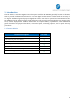
Document Change History Revision 1.0 1.
1. Introduction The XT-1010 is a wireless ZigBee sensor that pairs with the XT-4860G5 generally known as the Base Unit to provide inclination data based on a 3-axis digital accelerometer readout with an accuracy of ±1 degree. Additional general purpose digital IO sensors can also be queried and transmitted to the XT-4860G5. The XT-1010 leverages a high efficiency solar energy harvesting platform to support long term, remote deployments without the burden of frequent battery replacement.
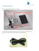
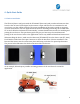
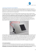
2. Hardware Description Below is a depiction of key interfaces of the XT-1010: ZigBee Pairing Button Device Label 8-Pin Bayonet Connector Solar Panel LED Indicators An optional Cable Harness that interfaces with the unit is shown below.
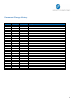
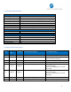
2.1 Hardware Specifications ZigBee Specification Technology Frequency Band Antenna gain Transmit power Data Rate Power Requirements D.C. Power (if Avail.) Battery Physical Connection Interface Connector Programming Mechanical Case Material Dimension Weight Operating Temperature Protection Rating ZigBee IEEE 802.15.4 DSSS modem 2405-2483.5MHz 0.5 dBi (peak again), -0.
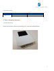
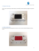
2.3 LED Description LED GPS (Green) Description Pairing Successful Stand-by for Pairing Status Solid for 30 Seconds then OFF Blinking Steadily 3. Device Mounting Options: 3.1 Screw Mounting The XT-1010 can be mounted via 4 mounting screw, 2 per side as depicted below.
3.2 Magnetic Mounting The XT-1010 can also be provided with 4 pre-installed (or kitted separately) magnets as depicted below. 3.3 VHB Tape Mounting For semi-permanent mounting option, the device can be mounted with 3M VHB tape as shown below.
4. Quick Start Guide 4.1 Device Installation The XT1010 (Sensor unit) pairs with the XT-4860G5 (Base unit) and provides inclinometer data based on the on-board 3-axis digital accelerometer output which in turn is transmitted to end user Server over the cellular network. The proper installation of the unit is critical to acquiring accurate inclinometer data.
4.2 Pairing the XT1010Z and the XT4860G5 With both Base and Sensor units properly oriented, the pairing process of the two devices can begin. Note that only one Sensor unit can be paired with one Base unit. During the pairing process, the devices are calibrated and normalized relative to each other. Once the calibration is complete, the Devices must not be moved or repositioned.
FCC/IC: REGULATORY COMPLIANCE INFORMATION This equipment with FCC-ID: GKM-XT1000 and IC: 10281A-XT-1000, Model: XT-1010 is subject to the Federal Communications Commission (FCC) and Industry Canada (IC) rules. NOTICE: Changes or modifications not expressly approved by the party responsible for compliance could void the user's authority to operate the equipment. This device complies with Part 15 of the FCC Rules and with license exempt Radio Standard Specifications of Industry Canada.