
User's Manual


7
Sales Engineering
support@xirgotech.com
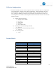
Cable Harness Specification:
24-pin Microfit: Molex 43025-2400
Panic SW/LED Button Conn. Molex 43020-0401 (4 pin 2 row female shell)
I-Button Conn.: Molex 43640-0201 (2 pin Female Shell)
Buzzer Conn.: Molex 43640-0301 (3 pin Female Shell)
Garmin Conn. Molex 43020-1001 (10 pin 2 row female shell)
Garmin pins 2 and 4 looped-in (black wire, 26 AWG)
Molex male pins: 43031-0002
Total length: 5 ft.
Pins 1, 3, and 5 are 18 AWG, All others are 24 AWG.
Fuse: 3A in line with pins with pins 1 (red) and 5 (white), 7 in. from wire end
Wires 1, 3, and 5 to be jacketed up to the fuse
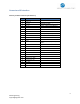
24-pin
No.
Color
Length
AWG
Pin function
Comments
I-Button
Buzz.
Panic SW
LED
Garmin
1
Red
60 in.
18
VBAT
3A fuse, 7 in. from end
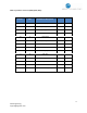
2
Orange
7 in.
20
LED+12V
3
3
Black
60 in.
18
Ground
4
White
7 in.
20
Ign Out
1
5
White
60 in.
18
IN0
3A fuse, 7 in. from end
6
Gray
60 in.
20
IN1
7
Brown
60 in.
20
IN2
8
Blue
7 in.
20
IN3
1
9
Red
60 in.
20
IN4
10
Brown
7 in.
20
OUT0
Buzzer GND
2
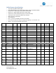
11
Orange
60 in.
20
OUT1
12
Yellow
7 in.
20
OUT2
4
13
Red
7 in.
20
Garmin PWR
12V/2A Switched
5
14
White/Brown
7 in.
20
Serial Port-1
TX
Garmin FMI Tx
1
15
Green
7 in.
20
Serial Port-1
RX
Garmin FMI Rx
6
16
Orange/Brown
7 in.
20
Serial Port-1
GND
Garmin FMI GND
4
17
Yellow
7 in.
20
Serial Port-2
TX
18
Green
7 in.
20
Serial Port-2
RX
19
Black
7 in.
20
Serial Port-2
GND
20
Gray
7 in.
20
1-Wire Serial
Main
i-Button
1