
User's Manual


Installation Guide: Proximity Tag Reader Installation Guide: Proximity Tag Reader
Installation
To install the PTR:
1 Select a location remembering that the detection zone is limited.
2 Use the PTR backplate as a template for locating mounting holes.
3 Drill a hole in the wall for the power wire. Route the power wire inside the wall in
accordance with the local wiring regulations in your district.
4Open the PTR case.
5 Push the power wire through the PTR backplate and work it towards the wiring
connector.
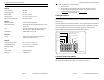
6 Connect the power wires as in Figure 8.
7 Optionally, connect the input wires as in Figure 8.
8 Set the PTR to Test Mode by setting the Mode Switches to 0, 0, 0. Mode Switches
are part of the Options DIP Switch and are shown in Figure 6.
9 Temporarily mount the PTR in its final location. Do not close the case.
10 Adjust the LF field. See “Setting LF Field Strength” on page 4.
11 Set the PTR address, and normal operating mode. See “Selecting an Operating
Mode” on page 5 and Table 1 on page 8.
12 Record the PTR address and location for later inclusion on the floor plan.
13 Close the enclosure.
14 Using the holes provided in the backplate, mount the PTR in its location. Use
fasteners such as screws or wall anchors so that, if required, the device can be
End of Procedure
removed from the wall, re-configured, and replaced in the same location.
Figure 8: 4 Pin Terminal Block Wiring
(Repeated for your convenience)
+ 12 VDC
Ground
Input
Ground
Page 10 981-000300-000 R1.00 (Draft)
If the PTR detects an input value different from the EOL values, it will respond as for an
error. Please see “Troubleshooting” on page 9.
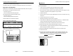
To enable an EOL input, turn Switch A of the Options DIP switch on. See Figure 7.
Edge Select in Standby Mode
Edge section is controlled by switch B in the Options DIP Switch shown in Figure 7.
Turn Switch B on to trigger the LF field on when:
the switch opens; or,
when a normally closed (NC) relay opens.
Turn Switch B off to trigger the LF Field on when:
the switch closes; or,
when a normally open (NO) relay closes.
These conditions are summarized in Table 2.
Figure 7: EOL and Edge Selection Switches
Table 2: Setting the LF Field Trigger
Switch Relay LF Field Switch B
Opens NC opens Turns on On
Closes NO closes Turns on Off
Page 9 981-000300-000 R1.00 (Draft)
EOL Switch
Edge Selection Switch
OPTIONS
ON
1 2 3 4 5 6 7 8
A B C D E F G H