
User's Manual


Installation Guide: Proximity Tag Reader Installation Guide: Proximity Tag Reader
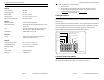
5 Use Figure 3 to identify the 3 Mode Switches: F, G, and H. Set all 3 Mode Switches to
0 as shown in Figure 3. This sets the PTR to Test Mode.
Figure 3: Mode Switches set in Test Mode
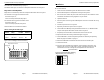
6 Temporarily mount the PTR in its final location and connect power as in Figure 4.
Figure 4: Power Wiring
7 Turn the LF field adjustment fully counter-clockwise. Do not turn the adjustment
forcefully to its limits. Do not needlessly wiggle or turn the adjustment.
8 Walk the tag to the detection area perimeter. Slowly turn the field adjustment
slightly clockwise. Stop turning when the red LED begins to blink.
9 Walk the Tag throughout the detection area to make sure that the LF field is
consistent throughout the area. If the LF field is inconsistent, turn the field
adjustment slightly counter-clockwise.
10 If you have increased the LF field strength, repeat Step 8 to ensure that the field
does not extend beyond the detection area.
Mode Switches
set to 0,0,0.
OPTIONS
Mode Switches
A B C D E F G H
ON
1 2 3 4 5 6 7 8
0 0 0
ON = 1
OFF = 0
+ 12 VDC
Ground
Input
Ground
Inputs are described
under “Standby Mode”
on Page 8.
Page 5 981-000300-000 R1.00 (Draft)
Appendix
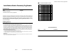
Figure 9: Address DIP Switch (Repeated for your convenience.)
In Table 5, the left hand column contains
the address. The columns, A – H, show
the switch positions: A black square
indicates the on position.
ADDRESS
ON
1 2 3 4 5 6 7 8
2
4
= 16
2
5
= 32
2
6
= 64
2
7
= 128
Least Significant Bit
A B C D E F G H
2
0
= 1
2
1
= 2
2
2
= 4
2
3
= 8
Table 5: Address Switch Positions
Address
ABCDEFGH
0
1
2
3
4
5
6
7
8
9
10
11
12
13
14
15
16
17
18
19
20
21
22
23
24
25
26
27
28
29
30
31
32
33
34
Table 5: (Continued) Address Switch
Address
ABCDEFGH