
Installation Manual


EXI HALO Installation Manual Rev 2.0
EXI Wireless Systems Inc. Page 10 June, 1999
3. INSTALLATION PROCEDURES
3.1. INSTALLING CONTROLLERS
3.1.1. PREPARE CONTROLLER FOR FIELD SET UP
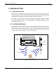
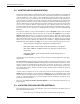
Figure 6 - HALO Controller Typical Hook-up Diagram
Assemble the controller pieces as illustrated in the above diagram. This is only a preliminary assembly
in order to set up the field. If necessary, obtain an AC extension cord so that the system may be tempo-
rarily energized at this location. Connect a user interface device such as a DKX Keypad. Make sure the
jumper on the back is in the maximum volume position so you can hear the beeper from a distance.
Check inside the controller to insure that the proper voltage is selected for the device you want to use.
PinPads use 5V while the Keypad requires 13V.
Install the RX antenna onto the Controller and plug in the R2-SRA. Try to place the RX antenna in the
approximate final location so that the test will be realistic. Open the controller cover and turn the ro-
tary Mode switch to position 0 for Test mode. In this mode the controller will turn on the beeper each
time it successfully reads a Tag. Connect the power supply and power-up. The frequency of beeping
will tell you how good the reception is.
Duct tape is metallic and
should never be used on the
SRA Exciter Antennae
The RX antennas can also be installed on a length of
coaxial cable when the best position for the antenna
is different than the best placement for the device.
The RX antenna should be oriented in the horizontal
plane with the maximum surface of the antenna ex-
posed to the longest distance requirement.
EXI ELECTRONIC SYSTEMS
Winnipeg, Manitoba (204) 788-1696
Made in Canada
PRODUCT
MODEL NO.
SERIAL NO>
ROAM II/TAGRRR
SEA-M
1118
"RX" Antenna
Keypad
"SRA"
Exciter Antenna
HALO "Controller"
1 2 3
4 5 6
7 8 9
*
0
#
Optional, to
Enhamce
Coverage
RECEIVE
ANTENNA
RBC
FCC ID# HE7MAX
TRANSMIT OUTPUT
SEA #1 SEA #2
Made in Canada . . with care
Controller
by
Power
1 2 3 4 5 6 7 8 9 10 11 12 13 14 15 16 17 18 19 20
+24V DC Input
System Ground
+12V Ou 200 ma
System Ground
Weigand 0/Data
Weigand 1/Gnd
System Ground
MagOut 24V 200 ma
Door Switch In
System Ground
Unlock In
Override In
Strobe In
N.O
COM
N.C.
N.O
COM
N.C
Relay #1 Relay #2
Alarm In
OFF ON