
Operations Manual


4.5. INSTALLING RECEIVERS
Receivers are meant for use where only a Tag Initiated Communications (TIC) signal needs to be
detected. These TIC signals originate from tags as a result of the tag sensing that it is being tampered
with.
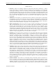
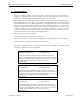
Figure 2 – HALO Receiver Configuration
The “Relay” light on the front of the receiver comes on to indicate relay activation when a “TIC” is
detected. The “Radio” light blinks when there is RF activity sensed on the radio channel. This activity
may be data from tags, or sometimes, intermittent presence of RF noise on the channel. When this
indicator is solid green, there may be a constant high-level RF noise source on the RF channel that
could block tag communications. The “Power” light has two functions, indicating that the Receiver has
been powered up when solid Red, and indicating activity on the RS-485 link when solid Green. This
indicator will alternate between Red and Green in the event the signals sensed on the RS-485
communications are unrecognizable, indicating potential RS-485 line communication trouble.
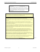
“Threshold” Switch
“0” = OFF
“F” = MAX sensitivity
Default = “F”
The R3 Controllers have unique serial numbers that are associated with the location that they serve.
Ensure that the correct Controller Serial Number is used at the location being entered on the floor
plan in the computer!
EXI HALO Installation & Operation Manual 981-000003-000R4.0
EXI Wireless Systems 23 October 2001