XOMAX XM-RSU248BT-B XM-RSU250B XM-RSU251R Installation Manual ENGLISH Montageanleitung DEUTSCH
Thema: DE Montage- und Kurzanleitung XM-RSU248BT-B XM-RSU250B XM-RSU251R Vielen Dank für Ihr Vertrauen, das Sie uns mit dem Kauf eines XOMAX Autoradios erwiesen haben. Wir wünschen Ihnen viel Spaß mit Ihrem neuen Multimedia Autoradio. i Bitte lesen Sie sich diese Montageanleitung sorgfältig durch, bevor Sie das Gerät installieren und in Betrieb nehmen. Bewahren Sie diese Anleitung auf, damit Sie auch später bei Unklarheiten nachschlagen können.
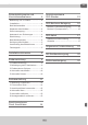
Thema: Sicherheitshinweise und Vorsichtsmaßnahmen DE 4 Anschlussschema ISO-Stecker 15 ISO-Buchsen-Belegung 16 Bedienung nur im Stand................... 4 Installation..................................... 4 Betriebslautstärke........................... 4 Buchse A (Stromversorgung)...........16 Reparatur des Gerätes..................... 4 Buchse B (Lautsprecher).................16 Stromversorgung............................. 4 Austausch von Sicherungen.............. 4 ISO-Kabel Überhitzung......
DE Thema: Sicherheit und Vorsichtsmaßnahmen Benutzen Sie das Gerät nicht weiter, wenn ein Problem oder Defekt auftritt. Überlassen Sie alle größeren Wartungs- und Instandsetzungsarbeiten einer qualifizierten Fachwerkstatt. Sicherheitshinweise und Vorsichtsmaßnahmen ! Bedienung nur im Stand ! Bei einem beschädigten Gewährleistungssiegel droht Gewährleistungsverlust. Um Unfälle zu vermeiden, bedienen Sie das Gerät bitte niemals während der Fahrt.
Thema: Sicherheit und Vorsichtsmaßnahmen DE Innentemperatur im Fahrzeug nicht über +60°C liegt. Ist es zu heiß im Fahrzeug, schalten Sie das Radio erst dann an, wenn die Innenraumtemperatur der Fahrgastzelle abgekühlt ist. ! Reinigung des Gerätes Halten Sie das Gerät sauber und befreien Sie es regelmäßig von Staub. Reinigen Sie das Gerät mit einem weichen und trockenen Tuch. Gröbere Verschmutzungen können mit einem feuchten Tuch abgewischt werden.
DE Thema: Installationshinweise »» Die Anschlusskabel dürfen nicht geschnitten bzw. kurzgeschlossen Installationshinweise werden. Die Folge wäre, der Verlust der Gewährleistung. ! Wir empfehlen, die Installation von einer fachkundigen Person oder einer Fachwerkstatt durchführen zu lassen. ! »» Bevor Sie das Gerät einbauen, stellen Sie sicher, dass das Fahrzeug über ein 12 Volt Bordnetz verfügt. »» Das Minus (-) muss an Masse (negativ) angeschlossen sein.
Thema: Installationshinweise DE »» Stellen Sie sicher, dass Sie das Negativ-Kabel (-) der Lautsprecher mit dem entsprechenden Negativ (-) Lautsprecheranschluss verbinden. Verbinden Sie niemals das Negativ-Kabel (-) der Lautsprecher mit der Autokarosserie. kann zu einem gefährlichen Kurzschluss führen. »» Verbinden Sie niemals die Lautsprecherkabel untereinander. Wenn Sie keine 4 Lautsprecher anschließen möchten, isolieren Sie die ungenutzten Kabelenden mit einem Isolierband, um Kurzschlüsse zu vermeiden.
Thema: Einbauanleitung DE Einbauanleitung i Bitte nehmen Sie zur Kenntnis, dass es sich hierbei um eine allgemeine Montageanleitung handelt und dass es vom Modell zum Modell durchaus zu diversen unwesentlichen Diskrepanzen führen kann, insbesondere bei den graphischen Darstellungen (z.B. bei der Art oder/und bei der Anwendung des Befestigungszubehörs). Eine ausführliche Bedienungsanleitung für Ihr Autoradio finden Sie auf unserer Internetseite unter: www.xomax.de/download 1 1 2 3 4 5 4.
Thema: Einbauanleitung DE 2 Fixierschraube befestigt werden, dass das Radio mit seiner Fixierschraube durch eines der Löcher des Fixierblechs geschoben werden kann. Später ( Seite 10 ) wird das Autoradio mit einer Mutter daran befestigt. 2 Befestigung des Fixierbleches Dieser Schritt kann nicht in jedem Fahrzeug ausgeführt werden. Daher kann er gegebenenfalls übersprungen werden. Das Fixierblech muss so am Fahrzeug 3 nenfalls muss auch die Blende entfernt werden.
DE Thema: Einbauanleitung 4 klick Fahrzeuges. Vergessen Sie nicht, die Radioantenne anzuschließen. 4 Autoradio anschließen Schließen Sie zunächst das ISO Kabel (falls vorhanden) an das Autoradio an. Danach verbinden Sie die ISO-Buchse mit den beiden ISO-Steckern Ihres Nun können Sie das Autoradio in den Rahmen einschieben, bis es mit einem leisen Klickgeräusch einrastet.
Thema: Ausbauanleitung DE Ausbauanleitung 1 Blech-Platinen, die in der Form variieren können. Die Ausziehschlüssel haben die Funktion, das Autoradio vom Einbaurahmen zu lösen. 1 Werkzeug vorbereiten Um das Autoradio auszubauen, benötigen Sie zunächst einen Schlüssel für die Mutter und zwei Ausziehschlüssel. Das sind in der Regel zwei flache Ausziehschlüssel befinden sich meistens im Lieferumfang Ihres Autoradios.
DE Thema: Ausbauanleitung 3 Ausziehschlüssel Die Schlüssel sollten mittig, mit gleichem Abstand nach oben und unten eingeführt werden. 3 Ausziehschlüssel verwenden Führen Sie nun die Ausziehschlüssel in die dafür vorgesehenen Aussparungen zwischen dem Einbaurahmen und dem Autoradio ein. 4 Seitenfixierungen lösen sich Die Fixierungen werden durch die Ausziehschlüssel gehalten. Solange die Schlüssel nicht entfernt werden, kann das Autoradio einfach herausgezogen werden.
Thema: Ausbauanleitung DE 5 Nach dem das Autoradio herausgezogen wurde, sollten alle Kabel abgeschlossen und der ISO-Stecker abgeklemmt werden. 5 Autoradio entfernen Ziehen Sie nun das Autoradio aus dem Radioschacht bzw. aus dem Einbaurahmen heraus. 6 6 Montagezubehör entfernen Wenn Sie das Radio nicht wieder einbauen möchten, kann im letzten Schritt das Montagezubehör (Fixierblech, Einbaurahmen) entfernt werden.
DE Thema: Anschlussschema Cinch Anschlüsse Anschlussschema Cinch Anschlüsse 14
Thema: Anschlussschema ISO-Stecker DE B A A Phantomeinspeisung Radio-Antenne Aktiv A4 A5 A7 A8 Dauerstrom Zündung + hinten rechts + vorne rechts + + vorne links + hinten links - Lautsprecher 12V 15 B 1 3 5 7 2 4 6 8 1 3 5 7 2 4 6 8 1357 2468 1357 2468 ISO-Stecker ISO-Kabel Anschlussschema ISO-Stecker
DE Thema: ISO-Buchsen-Belegung ISO-Buchsen-Belegung A 2 4 6 8 1 3 5 7 2 4 6 8 Buchse A (Stromversorgung) 1 3 5 7 B Buchse B (Lautsprecher) Auf der Seite A finden Sie die Buchse für die Stromversorgung. Auf der Seite B befinden sich die Lautsprecher-Anschlüsse.
Thema: ISO-Kabel DE ISO-Kabel 2 1 2 3 Kabelbaum-Beschreibung Hinweise 1. Stecker Mit diesem Stecker wird das ISO-Kabel an das Autoradio angeschlossen. »» Der Kabelbaum kann abhängig vom Gerätemodell variieren. Einheitlich ist dabei die Belegung der Lautsprecherkabel und die Stromzufuhr (Dauerplus, Zündungsplus und die Masse). 2. Sicherungen Die Sicherung kann in Form, Farbe und Ihren Eigenschaften abweichen.
DE Thema: Allgemeine Problemlösung Allgemeine Problemlösung Diese Problemlösungsvorschläge sind allgemeingültig und beziehen sich auf verschiedene XOMAX Modelle mit ähnlichen Eigenschaften. Bitte beachten Sie, dass einige Punkte sich nicht auf Ihr Autoradiomodell beziehen könnten oder dass Funktionen beschrieben sind, welche Ihr Gerät eventuell nicht unterstützt. Problem Ursache und Lösung Die Fernbedienung funktioniert nicht. Lösung 1: Prüfen Sie, ob die Batteriefolie entfernt wurde.
Thema: Allgemeine Problemlösung Das Gerät lässt sich nicht einschalten. DE Dieses Problem ist in den meisten Fällen auf einen fehlerhaften Anschluss des ISO-Kabels zurückzuführen. Überprüfen Sie die Belegung des ISO-Steckers und der Buchse. Achten Sie insbesondere auf die korrekte Belegung der Zündungsplus- und Dauerstrom-Verbindungen und korrigieren Sie Unstimmigkeiten. Hinweis: Die Bauform von ISO-Steckern und ISO-Buchsen ist zwar genormt, deren Belegung allerdings nicht.
DE Thema: Alt-Geräteentsorgung/Batterieentsorgung Alt-Geräteentsorgung Batterieentsorgung Im Rahmen der Batterieverordnung weisen wir Sie darauf hin, dass Sie verpflichtet sind, Batterien und Akkus in den Sondermüll, z. B. an kommunale Sammelstellen, zu entsorgen.
Topic: EN Installation Manual XM-RSU248BT-B XM-RSU250B XM-RSU251R Thank you for purchasing one of our XOMAX products! We appreciate your confidence. Enjoy your brand new multimedia unit! i Please read the following manual carefully before you install and use the unit. Please save this manual in case you will need to clarify further possible questions regarding installation and usage of our product. We recommend you to let the technician install the unit in your vehicle.
EN Topic: Safety instructions and precautions 23 Connection schedule – ISO plug 34 ISO plug configuration 35 Handling by stop only......................23 Installation....................................23 Regular loudness............................23 Socket A (power supply)..................35 Repair of the unit...........................23 Socket B (loud speakers).................35 Power supply.................................23 Replacement of fuses......................
Topic: Safety instructions and precautions Leave all the repair operations to professional technicians. Safety instructions and precautions ! Due to flawed warranty seal the warranty becomes invalid. ! Handling by stop only ! Power supply To avoid any accidents please don't handle the unit while you driving. Please stop and park the vehicle at safety place and handle the unit casually. ! EN Use the unit connected only to 12 Volt on-board power supply.
EN Topic: ! Safety instructions and precautions Cleaning of the unit Please keep the unit clean and remove the dust from it regularly. Please use for that a soft and dry cleaning rag. Major soilings can be removed carefully with the wet cleaning rag. Do not use any chemical or alcohol-containing detergents to avoid the damage of the unit's varnish. ! Moisture To avoid the danger of fire or the electric shock do not put the unit in to the moist environment (e.g.
Topic: Installation EN with the ground (GND) (negative). Installation »» Please tag the polarity of the available speakers before you disconnect the vehicle battery. ! We recommend you to let a professional technician install the unit in your vehicle. ! »» A proper grounding of the unit's housing requires a clean ground connection. Thus the grounding area should be rust-, stain- and dust-free.
EN Topic: Installation »» The speakers should feature the impedance of 4-8 Ohm and a sufficient wattage. »» Please ensure that the speakers you are connecting with the unit are intact. Damaged speakers can impair the unit. »» To avoid a short circuit please isolate all cable junctions and endings of the unused cables with the electrical tape. »» All the cables should be layed and fixated tidy and properly. The cables should not contact any movable or hot objects.
Topic: Installation instructions EN Installation instructions i Please note, that this installation manual was generalized attending to provide you with the common indispensable information. Therefore it might cause from product to product some irrelevant discrepancies, especially regarding some depictions (e.g. installation accessories) You can find the detailed manual for your XOMAX product on our homepage: www.xomax.de/download 1 1 2 3 4 5 3. dual-ended bolt 1 Installation steps 4. unit 1.
EN Topic: Installation instructions 2 dual-ended bolt then the dual-ended bolt of the unit should be pulled through one of the holes in the fixation metal sheet. 2 Fixture of the fixation sheet This step can not be accomplished in every vehicle, thus it may be possibly skipped. The fixation metal sheet should be fixated in the vehicle first, Later ( see page 29 ) the unit will be fixed to the metal sheet with the washer and the nut.
Topic: Installation instructions EN 4 click Now slide the unit carefully into the already fixated frame till it clicks into place. 4 Connect the unit Please connect the ISO cable first with the ISO plug of the unit, then with the one of the vehicle. Do not forget to connect the radio aerial. 5 fixation metal sheet fixation bolt fixation nut the fixation metal sheet. Now the unit should be fixated to the metal sheet with the washer and the nut.
EN Topic: Deinstallation instructions Deinstallation instructions 1 to release the unit from the installation frame. 1 Prepair the instruments To deinstall the unit you will need a spanner (a wrench) to unloose the fixation nut and 2 extraction keys (optional) 2 unloose the fixation nut This step may be possibly skipped, if due to the lack of space the unit initially was not fixated to the fixation metal sheet.
Topic: Deinstallation instructions EN 3 extraction keys In each case the key should be inserted centered, the inserting point should be equally distanced both from the top and from the bottom. 3 Use the extraction keys Please insert the extraction keys into the dedicated recesses between the installation frame and the unit's housing. 4 unlocking holding side-cogs can be carefully pulled out.
EN Topic: Deinstallation instructions 5 Afterwards please disconnect all the cables incl. the ISO multicore. 6 Remove the unit Now pull the unit carefully out of the installation frame or out of the car radio slot in case the frame was already firmly fixed to the unit by delivery. 6 5 Remove the installation accessories Finally remove all the installation accessories such as fixation metal sheet and installation frame.
Topic: Connection schedule – Cinch multicore Connection schedule – Cinch multicore 33 EN
Topic: Connection schedule – ISO plug B A A phantom power radio aerial active A4 A5 A7 A8 permanent current ignition + rear right + front right + front left + rear left - 12V loud speakers - 34 B 1 3 5 7 2 4 6 8 1 3 5 7 2 4 6 8 1357 2468 1357 2468 ISO plug ISO cable Connection schedule – ISO plug + EN
Topic: ISO plug configuration EN ISO plug configuration A 2 4 6 8 1 3 5 7 2 4 6 8 Socket A (power supply) 1 3 5 7 B Socket B (loud speakers) On the A side you can find the socket for power supply. On the B side you can find the speakers terminals.
EN Topic: ISO cable connections ISO cable connections 2 1 2 3 ISO cable connections Please note 1. Terminal plug »» The multicore cable may vary depending on the current model. Though the configuration of the loud speakers- and power supply- cables (steady plus, ignition plus, ground) is consistent. 2. Fuses 3. ISO-plug This plug connects the ISO cable with the vehicle.
Topic: Common solutions EN Common solutions The following advices are generally valid and refer to diverse Xomax models with the similar characteristics. Please note that some articles may refer not to your model exactly and contain the describtion of features and functions that your model does not support. The describtion of the problem The cause and the solution The remote control is without function. Solution 1: Please ensure that the battery film is removed.
EN Topic: Common solutions Poor radio reception: The radio tuner finds no broadcaster or the reception is poor. For problem-solving regarding the radio reception it is important to know the type of the antenna of your vehicle. Here are the possible solutions for each type of the antenna: Type 1 – passive antenna ( see page 33 – wiring diagram): We recommend you to substitude the existing antenna by the larger and therefore more efficient one.
Topic: Recycling of an old unit/Recycling of the battery Recycling of an old unit Recycling of the battery User information regarding recycling of electric and electronic devices (private households) According to the battery decree we make you aware of your obligation to dispose of empty batteries at municipal collection points. Batteries that contain pollutants (e.g. Hg = mercury, Pb = lead, Cd = cadmium) are labelled with the symbol pictured above.