OWNER’S MANUAL
Table of Contents Product Registration ..2 Important Safety Instructions .. 3 Important Electrical Information .. 4 Important Operation Instructions .5 Assembly instructions 6 Operation of Your New Treadmill .. .10 General Maintenance.
CONGRATULATIONS ON YOUR NEW TREADMILL AND WELCOME TO THE XTERRA FAMILY! Thank you for your purchase of this quality treadmill from Xterra. Your new treadmill has been manufactured by one of the leading fitness manufacturers in the world and is backed by one of the most comprehensive warranties available. Xterra will do all we can to make your ownership experience as pleasant as possible for many years to come.
Important Safety Instructions WARNING - Read all instructions before using this appliance. DANGER - To reduce the risk of electric shock disconnect your Xterra treadmill from the electrical outlet prior to cleaning and/or service work. WARNING - To reduce the risk of burns, fire, electric shock, or injury to persons, install the treadmill on a flat level surface with access to a 120-volt, 15-amp grounded outlet. DO NOT USE AN EXTENSION CORD UNLESS IT IS 14AWG OR BETTER, WITH ONLY ONE OUTLET ON THE END.
Important Electrical Information WARNING! NEVER use a ground fault circuit interrupt (GFCI) wall outlet with this treadmill. Large switching currents of the drive motor will trip GFCI type outlets, as any appliance with a large motor will. Route the power cord away from any moving part of the treadmill including the elevation mechanism and transport wheels. NEVER remove any cover without first disconnecting AC power.
Important Operation Instructions NEVER operate this treadmill without reading and completely understanding the results of any operational change you request from the computer. Understand that changes in speed and incline do not occur immediately. Set your desired speed on the computer console and release the adjustment key. The computer will obey the command gradually. NEVER use your treadmill during an electrical storm. Surges may occur in your household power supply that could damage treadmill components.
Assembly Instructions for TR250 and TR350 ASSEMBLY PACK CHECK LIST #111 - M5 x 15mm #95 - 5/16 x 19mm Phillips Head Screw (8pcs) Curved Washer (4pcs) #94 - 5/16 x 15mm #110 - 5/16 x 19mm Button Head Socket Bolt (14pcs) Flat Washer (10pcs) #102 - Safety Key (1pc) #93 - Lubricant (1pc) #97 - Combination M5 Allen Wrench & Phillips Head Screw Driver (1pc) #98 - M6 Allen Wrench (1pc) 6 TR450_TR550 Treadmill
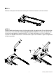
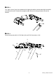
STEP 1 Remove all the parts from the carton and lay the main base frame on a flat level surface. STEP 2 Feed the cable from the base frame (38) through the right side upright tube (5) and slide the tube into the base frame tube. Be careful not to pinch the wire harness. Install the left upright tube (4) and just hand tighten for now all eight 5/16 x 1/2 bolts (94) and the six 5/16 flat washers (110) for the side bolts and two 5/16 curved washers (95) for the front bolts.
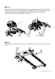
STEP 3 This step is easier if you have someone else helping to hold the console mounting frame while you connect the wire. Connect the computer cable (38) to the mating connector (36) of the console. 36 38 STEP 4 Secure the console with six 5/16 bolts (94) and 5/16 flat washers (110).
STEP 5 Connect all six connectors to the mating connectors on the back of the console. There are two 3-pin connectors that are color coded, make sure to plug them into the correct place. There are two 2-pin connectors that can be plugged into either mating connector on the console. Secure the console with four M5 X 15mm screws (111). 39 112-3 27 36 25 27 26 STEP 6 Attach the left (44) and right (43) covers to the upright base frame with four M5 X 15mm screws (111).
Operation of your new Treadmill Getting started: Power the treadmill on by plugging it into an appropriate wall outlet, then turn on the power switch located at the front of the treadmill below the motor hood. Ensure that the safety key is installed, as the treadmill will not operate without it. When the power is turned on, a message will scroll across the dot matrix showing the current software version.
Quick-Start Operation: STEP 1: Attach the Safety key to enable the display (if not already on). STEP 2: Press the Start key to begin belt movement. Then adjust to the desired speed using the Fast / Slow keys (console or handgrip). You may also use the rapid speed keys 2 through 10 to adjust the speed. STEP 3: To slow tread-belt press and hold the Slow key (console or handgrip) to the desired speed. You may also press the rapid speed adjust keys, 2 through 10.
Dot Matrix Center Display (Program Operation): Twenty rows of dots (8 high) indicate each segment of a workout. The dots are only to show an approximate level (speed/incline) of effort. They do not necessarily indicate a specific value only an approximate percent to compare levels of intensity. In operation the Speed / Incline dot matrix window will build a profile picture as values are changed during a workout.
Programmable Features The TR450 has five factory preset programs, two user defined programs, two heart rate control programs and one Manual program. The TR550 has nine factory preset programs, two user defined programs, two heart rate control programs and one Manual program. Each preset program has a maximum speed level that is displayed when a desired workout is chosen. The maximum speed that the particular program will achieve will be displayed in the Speed window.
XTERRA TREADMILL PROFILES (TR450/TR550) 14 TR450_TR550 Treadmill
User Programs: STEP 1: Select User 1 or User 2 via the PROGRAM key then press Enter. Note that the dot matrix display portion will have a single row of dots at the bottom (Unless there is a previously stored program). STEP 2: Note the Time window is flashing. Use the Adjust UP/DOWN keys to adjust up from 10 minutes (if desired). Press ENTER key. This is a must to continue even if time is not adjusted. STEP 3: The Calorie window will now be blinking a bodyweight value. Enter your bodyweight and press Enter.
Heart Rate Control Operation How the Heart Rate Control Program Works: Heart Rate Control uses your treadmill s incline system to adjust your heart rate. Increases and decreases in elevation affect heart rate much more efficiently than changes in speed. Additionally, changes in incline keep you in control of the machine s speed instead of the machine controlling you.
General Maintenance Belt and Bed - Your treadmill uses a very high-efficient low-friction bed. Performance is maximized when the bed is kept as clean as possible. Use a soft, damp cloth or paper towel to wipe the edge of the belt and the area between the belt edge and frame. Also reach as far as practical directly under the belt edge. This should be done once a month to extend belt and bed life. Use water only - no cleaners or abrasives.
TREADBELT TRACKING ADJUSTMENT: The performance of your treadmill is dependent on the frame running on a reasonably level surface. If the frame is not level, the front and back roller cannot run parallel, and constant belt adjustment may be necessary. The treadmill is designed to keep the tread-belt reasonably centered while in use. It is normal for some belts to drift near one side while the belt is running with no one on it.
BELT / DECK LUBRICATION: Do not lubricate with other than Xterra approved lubricant. Your treadmill comes with one tube of lubricant and extra tubes can be ordered directly from Xterra. There are commercially available lube kits, but the only one currently approved by Xterra is Lube-N-Walk. These kits come with an application wand that makes applying the lubrication easier. The kits can be purchased from Xterra or directly from Lube-N-Walk here: http://www.jadfitness.
Service Checklist - Diagnosis Guide Before contacting your dealer for aid, please review the following information. It may save you both time and expense. This list includes common problems that may not be covered under the treadmill s warranty.
Manufacturer s Limited Warranty Effective July 15, 2009 TREADMILL LIMITED WARRANTY Xterra Fitness Inc. warrants all its home use treadmill parts for a period of time listed below, from the date of retail sale, as determined by a sales receipt or in the absence of a sales receipt, eighteen (18) months from the original factory shipping date.