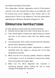
User Manual PS70PRO Smart Diagnosis System Shenzhen Xtooltech Intelligent Co.
Please read this user manual carefully before using the PS70PRO Smart Diagnosis System. When reading the manual, please pay attention to the words “Note” or “Caution”, and read them carefully for appropriate operation. TRADEMARKS is a registered trademark of Shenzhen Xtooltech Intelligent CO., LTD.
COPYRIGHT Without the written consent of Shenzhen Xtooltech Intelligent Co., Ltd., any company or individual shall not copy or backup this operation manual in any form (electronic, mechanical, photocopying, recording, or other forms). DECLARATION This manual is designed for the usage of the PS70PRO Smart Diagnosis System and provides operating instructions and product descriptions for users of the PS70PRO Smart Diagnostic system.
the product according to the manual. The configuration, function, appearance and UI of this product involved in the user manual will continue to be optimized, and the manual may not be updated in time. Please refer to the actual product if there is any difference. The final interpretation right belongs to Shenzhen Xtooltech Intelligent Co., Ltd. OPERATION INSTRUCTIONS For safe operation, please follow the instructions below: Keep the device away from heat or fumes when you use it.
Do not switch off the power or unplug the connectors during testing, otherwise, you may damage the ECU and/or the Diagnostic Computer. CAUTIONS! Avoid shaking or dismantling the unit as it may damage the internal components. Do not use hard or sharp objects to touch the LCD screen; Do not use excessive force; Do not expose the screen to strong sunlight for a long period. Please keep it away from water, moisture, high temperature, or very low temperature.
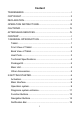
Content TRADEMARKS.................................................................................... I COPYRIGHT....................................................................................... II DECLARATION...................................................................................II OPERATION INSTRUCTIONS....................................................... III CAUTIONS!........................................................................................IV AFTERSALES-SERVICES.........
3 UPDATE......................................................................................... 16 4 DIAGNOSIS........................................................................................ 18 Vehicle Connection.................................................................... 18 Diagnosis..................................................................................... 19 Vehicle Selection........................................................................ 20 Basic functions...........
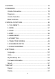
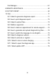
File Manager............................................................................... 61 8 REMOTE ASSISTANCE...................................................................62 9 FACTORY RESET.............................................................................65 10 FAQ.................................................................................................... 71 Q1: Failed to generate diagnosis report................................. 71 Q2: How to print diagnosis report.............
1 GENERAL INTRODUCTION The XTOOL PS70PRO smart diagnostic system is an advanced flatbed scanning tool based on the Android operating system. It supports multi-language switching and is suitable for different countries and regions.
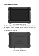
FRONT VIEW OF TABLET Fig 1-1 Sample of Tablet Front View The front of the main unit is a touchable display screen, you can use your fingers to operate on the screen to complete the car diagnosis.
The product model and S/N are laser-engraved on the back of the display tablet, and the small hole at the bottom is the Loudspeaker. 1 Nameplate: Display basic information such as S/N and model etc. 2 Loudspeaker: external sound can be played, supporting the playback of music, etc. HOST PORTS Fig 1-3 Sample of Host Ports on Tablet ① Micro USB: Battery charge or data synchronization with PC or DC. ②DB15 Port: This port is used to connect to the main test cable.
TECHNICAL SPECIFICATIONS Table 1-1 Specification Item Description Operating System Android Processor Quad-core 1.6GHz Processor Memory 32GB Display 7.0-inch touch screen with 1024×600 resolution Connectivity Sensors Gravity sensor, light sensor Auto Input/Output Microphone, speaker Power and Battery 4000mAh, 3.
PACKAGE KIT MAIN UNIT Tablet 1 pcs OTHER ACCESSORIES OBDⅡ-16 Connector (1 pcs) * Used to connect the main cable and the car. Main Test Cable (1 pcs) *The main cable is used to connect the Tablet to the connector. USB Cable(1 pcs) *Connect the table to the PC or DC power adapter. Power Adapters a) DC5V 2A charger 1pcs b) AC Charger Adapter 1 pcs (EU Standard) c) AC Charger Adapter 1 pcs (US Standard) *Used to connect a USB cable to an external DC power port for charging.
2 GETTING STARTED ACTIVATION After first-time users press and hold the power button to turn on the system, the system will automatically enter the guide process and request to select the language for the operating system. Fig 2-1 Select Language before Activation After setting the system language, you will enter the activation page, as shown in the figure below. You can also click the "Trial" button in the upper right corner to try it out before activation.
Fig 2-2 Sample of Start Activate Click Start Activate to enter the activation page, as shown below: Fig 2-3 Input your Email Address in the Field 7
A pop-up window showing Activation Success indicates that you have completed the first boot setup, click OK to enter the diagnostic system and start using the device.
MAIN INTERFACE OPERATION SYSTEM As shown in the figure below, this interface is the main page of the operating system of the device. You can also return to this interface at any time by clicking 【⚪ 】on the bottom navigation bar.
Table 2-1 Items Descriptions Browser Album Application Square File Explorer Settings for Android System a) Browser: Click on the browser icon to enter the browser to view the official website of XTOOL or search for other information. b) Gallery: Click the Gallery icon to enter the album to quickly view the pictures or screenshots stored in the device.
Fig 2-6 Sample of Application Square d) ES File Explorer: You can manage APP, music, files, pictures, etc. in the device in this function, and you can also use Local/Home/Cleaner to clean up files. DIAGNOSIS SYSTEM ENTRANCE Once activated, you will automatically enter the diagnostic system with the following main screen.
Fig 2-7 Sample of Smart Diagnosis System Homepage The main interface is mainly composed of Function Buttons and Navigation Buttons. The touch screen navigation is menu-driven, and you can quickly access functions by clicking on the option title and answering the dialogue window. A detailed description of the menu structure can be found in the next section Function Buttons.
FUNCTION BUTTONS The following table briefly describes each function button Table 2-2 Item Description Quickly access to the vehicle system to identify the vehicle VIN code Enter to select a vehicle Includes special functions for car diagnosis You can view the vehicle diagnostic report In case of failure, you can control the diagnostic equipment remotely Users can upgrade the available software with one click Users can set the language, unit, Bluetooth, repair shop information, also can view information a
NAVIGATION BUTTONS Instructions for operating the navigation bar buttons at the bottom of the screen, as described in the table below: Table 2-3 Items Descriptions Back to the previous interface Back to the main interface of the Android system Shows recently used applications Press for screenshot Increase volume Display bluetooth statu Decrease volume Click here to return to the diagnostic vehicle models interface Screen recorder 14
NOTIFICATION BAR Slide down to open the notification bar. Users can adjust the brightness of the screen when they need it, and you can also connect Wi-Fi and so on.
3 UPDATE After activating the device, please update the software in "Update" first. The device will pull all currently supported software packages, and you can download them as needed. ALL software updates directly via the Internet.
Fig 3-2 Sample of Updating *Xtool Devices support bilingual upgrades, usually English and the local language. To switch other languages, please contact your dealer.
4 DIAGNOSIS The diagnostic application can read ECU information, read and clear DTC and check living data and freeze frames. The diagnosis application can access the electronic control unit (ECU) of various vehicle control systems, including the engine, transmission, anti-lock braking system (ABS), airbag system (SRS), and perform kinds of actuation tests.
The connection method is shown in the figure below: Fig 4-1 Sample of How to Connect Vehicle & Device 1 Tablet 2 Main Test Cable 3 OBDII-16 Connector 4 Vehicle *Caution: Please make sure all the cables are connected tightly; The vehicle’s DLC is not always located under the dash; for the location of the DLC, please refer to the vehicle’s user manual. DIAGNOSIS After the tablet device is properly connected to the vehicle, the system can begin vehicle diagnosis.
Fig 4-2 Sample of Europe Vehicles *Note: OBDⅡ supports reading the common fault codes in the engine; DEMO, a demonstration program. Click this button to experience and learn the operation process of the diagnostic function. VEHICLE SELECTION PS70PRO Smart Diagnosis System supports 2 ways to access the vehicle diagnosis system. You can select "Automatic Detection" or "Manual Selection" to enter the diagnosis system.
Enter "manual selection", you can also diagnose the car according to the system according to your needs after selecting the model.
Fig 4-4 Sample of Basic Functions Read ECU Information: This function is to read ECU version information, which is the equivalent of "System Identification" or "System information in some electronic control systems, all mean to read ECU related software and hardware versions, models, and production date of diesel engine, part number, etc. It is convenient for us to make a record in the maintenance process, and it also makes data feedback and management easier.
Fig 4-5 Sample of ECU Info Read Trouble Code: Read trouble codes stored in ECU.
*Tip: In the process of diagnosis, if the device shows “System is OK” or “No Trouble Code”, it means there is no related trouble code stored in ECU or some troubles are not under the control of ECU, most of these troubles are mechanical system troubles or executive circuit troubles, it is also possible that signal of the sensor may bias within limits, which can be judged in Live Data.
Suggestion: users should better not clear trouble codes, we need to record the trouble details after reading the code, which is provided as a reference for maintenance. After dealing with troubles, there will be no trouble code when we re-read. Read Live Data: that is to read the parameters of running engine, such as oil pressure, temperature, engine speed, fuel oil temperature, coolant temperature, intake air temperature, etc.
Fig 4-9 Sample of Multi-line Chart In the process of diagnosis, if the device shows “System is OK” or “No Trouble Code”, it means there is no related trouble code stored in ECU or some troubles are not under the control of ECU, most of these troubles are mechanical system troubles or executive circuit troubles, it is also possible that signal of the sensor may bias within limits, which can be judged in Live Data.
This function allows the device to send information to and receive information from, vehicle control modules. For example, in the case of OBD II generic information Mode 1 (which relates to data parameters), the scan tool user initiates a request for information from the powertrain control module (PCM), and the PCM responds by sending the information back to the scan tool for display. Most enhanced scan tools also can actuate relays, injectors, and coils, perform system tests, etc.
5 SPECIAL FUNCTIONS The PS70PRO Smart Diagnosis System supports 23 commonly used special reset functions, allowing you to quickly access your vehicle system for various scheduled services, maintenance, and reset performance, eliminating the need to reset after resolving common problems. This user manual lists some of the commonly used special reset services for your reference.
5.1 OIL RESET Reset the Engine Oil Life System, which calculates the optimum oil life change interval based on the vehicle’s driving conditions and climate. The oil life reminder must be reset each time the oil is changed so that the system can calculate when the next oil change is required. This function can be performed in the following cases: If the service lamp is on, you must provide service for the car.
Figure 5-2 Sample of oil reset function (screen 1) 3. 4. Enter Maintenance mileage reset menu. Input reasonable value of mileage and press OK. Figure 5-3 Sample of oil reset function (screen 2) 5. Message of ‘Reset success’ displayed when Oil Reset function has successfully performed.
5.2 EPB Electronic Parking Brake (EPB) System reset is a popular special function. You can use this function to reset the electronic parking brake system and brake pads, which also supports the brake pad replacement (retraction, release of the brake pump), G-sensor, and body angle calibration. This function has multiple uses and can safely and effectively maintain the electronic brake system.
Figure 5-4 Sample of EPB function (screen 1) 3. Enter the Enter maintenance mode menu and release the handbrake brake. And press OK after completing the instructions shown. Figure 5-5 Sample of EPB function (screen 2) 4. 5. Wait until the message of ‘Successful operation’ popes up. And press OK to exit the menu. Enter the Exit maintenance mode menu and wait until the message of ‘‘Successful operation’ popes up.
5.3 SAS Steering Angle Sensors (SAS) System Calibration permanently stores the current steering wheel position as the straight-ahead position in the SAS EEPROM. Therefore, the front wheels and the steering wheel must be set exactly to the straight-ahead position before calibration. In addition, the VIN is also read from the instrument cluster and stored permanently in the SAS EEPROM. On successful completion of calibration, the SAS fault codes will be automatically cleared.
Figure 5-6 Sample of SAS function (screen 1) 3. Wait until the following instruction is displayed and press Yes after completing the instructions shown.
4. Follow the instructions displayed and press OK after completing the instructions shown. Figure 5-8 Sample of SAS function (screen 3) 5. Wait until the following instruction is displayed and press OK after completing the instructions shown.
6. Message of ‘Function execution is completed’ displayed when SAS function has successfully performed. 5.4 DPF The Diesel Particle Filter (DPF) function manages DPF regeneration, DPF component replacement teach-in, and DPF teach-in after replacing the engine control module (ECM). The ECM monitors driving style and selects a suitable time to employ regeneration. Vehicles driven a lot at idling speed and low load will attempt to regenerate earlier than vehicles driven more with higher load and speed.
The operation guidelines of the DPF function are shown as below: 1. Enter the DPF menu and choose relevant models according to the vehicle being tested. 2. Enter the DPF regeneration menu. 3. Read carefully and complete the requisites listed before performing the DPF regeneration function. And press OK after completing the instructions shown. Figure 5-10 Sample of DPF function (screen 1) 4. 5. 6. Read the fuel tank level and make sure that it fulfills the requirement displayed.
Figure 5-11 Sample of DPF function (screen 2) 7. Read the note carefully and follow the instructions shown on the screen. And press OK after completing the instructions shown.
8. Follow the instructions displayed and press OK after completing the instructions shown. Please pay attention to the Note. Figure 5-13 Sample of DPF function (screen 4) 9. Press the OK button to start the regeneration.
10. Wait for the value of carbon deposit to decrease until a message of ‘Emergency regeneration has been completed’ popes up, this process may take up to 40 minutes. Figure 5-15 Sample of DPF function (screen 5) 11. Wait for 2 minutes to let the particulate filter cool down. Figure 5-16 Sample of DPF function (screen 6) 12. Press drop out to exit the DPF function.
5.5 BMS RESET The Battery Management System (BMS) allows the scan tool to evaluate the battery charge state, monitor the close-circuit current, register the battery replacement, and activate the rest state of the vehicle. This function enables you to perform a resetting operation on the monitoring unit of the vehicle battery, in which the original low battery fault information will be cleared and battery matching will be done.
1. Enter the BMS Reset menu and choose relevant models according to the vehicle being tested. 2. Turn on the ignition switch. 3. Press OK to continue the BMS function. 4. Enter battery capacity (within the given range) and press OK after the input. Figure 5-17 Sample of BMS function (screen 1) 5. Enter the battery manufacturer and press OK after the input.
Figure 5-18 Sample of BMS function (screen 2) 6. Enter the 10-digit battery serial number and press OK after the input.
5.6 THROTTLE Throttle Position Sensor (TPS) Match, this function enables you to make initial settings to throttle actuators and returns the “learned” values stored on ECU to the default state. Doing so can accurately control the actions of regulating throttle (or idle engine) to adjust the amount of air intake. The operation guidelines of the Throttle function are shown as below: 1. Enter the Throttle menu and choose relevant models according to the vehicle being tested. 2.
4. Wait until all the parameters are read and displayed. Figure 5-21 Sample of throttle function (screen 2) 5. Press the F2 button and wait until a message of ‘Match successfully’ pops up.
5.7 INJECTOR CODING This function can write the identification code of the fuel injector into the ECU so that the ECU can recognize and work normally. Write actual injector code or rewrite code in the ECU to the injector code of the corresponding cylinder for controlling accurately and correcting cylinder injection quantity.
Figure 5-22 Sample of injector coding function (screen 1) 4. Read and confirm the value stored in the cylinders.
5. Enter the Change the value of cylinder menu of the replaced injector(s), enter the new 5-digit value, and then press OK. Figure 5-24 Sample of injector coding function (screen 3) 6. 7. 8. 9. Wait until the message ‘Write successfully’ pops up. Turn off the ignition switch. Wait until the message asked you to turn on the ignition switch. Re-enter the Fuel injection nozzle injection volume adjustment menu to check whether the new value(s) are shown.
5.8 GEARBOX MATCH After changing the gearbox or changing the gearbox ECU, you need to use the gearbox matching function to re-match the engine and the gearbox. Before resetting the gearbox, please check the gearbox control unit to ensure that there is no fault code. If there is a fault code, the gearbox memory function cannot be reset. Please road test after reset. The operation guidelines of the Gearbox Matching function are shown as below: 1.
5.9 GEAR LEARNING The crankshaft position sensor learns crankshaft tooth machining tolerance and saves to the tablet to more accurately diagnose engine misfires. If gear learning is not performed for a car equipped with a Delphi engine, the MIL turns on after the engine is started. The diagnostic device detects the DTC P1336 'Gear not learned'. In this case, you must use the diagnostic device to perform gear learning for the car. After gear learning is successful, the MIL turns off.
Figure 5-27 Sample of gear learning function (screen 1) 5. Read the instructions displayed and press Yes to start the learning process.
6. Press the accelerator pedal down and hold it until a message of ‘The learning is successful, please release the accelerator pedal.’ pops up. 7. Release the accelerator pedal and press OK to exit the gear learning function. 6 SETTINGS Click the Settings button to adjust the default settings and view information about the PS70PRO Smart Diagnosis System.
After the configuration is successfully changed, you can switch the target language. Fig 6-1 Sample of Language Settings This will only change the language of the APP. If you want to change the system language, please go to Android Settings. How to change the language of your software? Step1: Contact your dealer and leave a message about the language you need and the S/N of your device, The technician will modify the language configuration for you in the background.
Note: The types and quantities of languages supported are subject to the actual language types displayed on the device Step4: Back to Updates to pull all packages again UNITS You can switch the unit used by the system. PS70PRO Smart Diagnosis System provides you with Metric, Imperial, and U.S. units. You can directly click on the unit you need, after the switch is successful, a blue checkmark will be displayed behind the unit’s name.
MY WORKSHOP INFO Click on My Workshop Information, you can input your workshop information here. As shown in the figure below, you just need to fill in the valid information in the corresponding column and click "SUBMIT". And then it will show your workshop information in the report when you generate a diagnostic report, including your company name, address, website, telephone, and mailbox.
FIRMWARE INFORMATION Fig 6-4 Sample of Firmware Information You can view the firmware information here, including the firmware name, the latest firmware version, the currently used firmware version, and the firmware type. The diagnosis tablet supports automatic firmware update, please make sure that the device is connected to the network when you enter the diagnostic software and the firmware will be automatically updated to the latest version.
ABOUT Tap on ABOUT, you can check the serial number and APP version on here.
7 REPORT Diagnostic Report is used for viewing and printing the saved files, such as Live Data, Trouble Codes, or pictures generated in the process of diagnosis, users also can view a record of which cars have been previously tested. It includes 3 parts: Report Replay File Management Fig 7-1 Sample of Report Function REPORT This feature provides a history of diagnostic reports, where you can view and delete the vehicle's diagnostic reports according to your needs.
Fig 7-2 Sample of Report Records When you open the report, located in the header of the table is the studio information you filled in advance in the system setup, then the information of the vehicle, as shown as below: Fig 7-3 Sample of Report Print PDF Report As you can see, you also could click " Print PDF Report " at the bottom right corner to output the pdf report. If you need to close the report, you could tap on the button “Exit”.
Please follow the below steps to print your report▼ Step 1: Install an APP that can drive your target printer. Add the printer and input the IP address of the printer in the APP, or you can contact your dealer for help. PS70PRO Smart Diagnosis System doesn’t provide the printer driver software, please install a third part App on the tablet if you need the print your diagnosis report. Step 2: Back to the Android main menu, go to Settings -> Printing-> Turn the printer on.
Before replaying the living data, please make sure you have recorded the live data during the diagnosis Fig 7-6 Sample of Live Data Replay FILE MANAGER This function allows you to check and delete files on the device. Please use this function under the guidance of professionals. Ordinary users are not recommended to use it by themselves, as it may cause software missing or malfunctioning.
8 REMOTE ASSISTANCE Tap on "Remote" to start the TeamViewer quick support program, which is a simple, fast, and secure remote-control screen. You can use this application to enable them to control your tablet on a PC through the TeamViewer software, thereby obtaining temporary remote support from XTOOL's technical support center. Computers and mobile devices running TeamViewer are identified by a globally unique ID.
Fig 8-1 Sample of Team Viewer Starting 2. Click Remote in the diagnosis application. The TeamViewer screen is displayed, and the device ID will be generated.
3. Your partner must install the remote-control software on his/her computer by downloading the full version of the TeamViewer program (http://www.teamviewer.com) online, and then start the software on his/her computer at the same time, to provide support and remote control of the tablet. 4. Provide your ID to the partner or XTOOL technician, and then wait for him/her to send you a remote-control request. 5.
9 FACTORY RESET Once the device is restored to factory settings, historical data cannot be restored. Please use this function under the guidance of professional technicians. Xtooltech is not responsible for all economic losses caused by restoring factory settings, please use this function with caution.
Step 2 Click on Factory Data Reset Fig 9-2 Sample of FACTORY RESET (Screen 2) Step 3 Click on Reset Device Fig 9-3 Sample of FACTORY RESET (Screen 3) 66
Step 4 Click on ERASE EVERYTHING Fig 9-4 Sample of FACTORY RESET (Screen 4) After you complete the above operations, the device will automatically restart and enter the factory mode to pull the new software. Please keep the network stable and follow the instructions on the page. You can select the language in the following interface.
Fig 9-5 Sample of Select Language After selecting the system language, click Next to enter the WiFi connection page, as shown below: Fig 9-6 Sample of Wi-Fi Connection Select a network to connect to on the Wi-Fi connection page.
After successful network connection, the automatic system will jump to Factory mode to download the software: Fig 9-7 Sample of Factory Mode Once the software has been downloaded, the tablet will automatically reboot and request the system language selection again.
Fig 9-8 Sample of Language Selection Since restoring the factory settings will erase the user information on your device, you need to enter the email again to Note Once the device is reset to factory settings, historical data cannot be recovered. Please use this feature with caution. In addition, if you restore factory settings after the expiration date, Xtooltech is not responsible for restoring historical data for you. It is recommended to use this function under the guidance of a technician.
10 FAQ Q1: FAILED TO GENERATE DIAGNOSIS REPORT 1. Currently only perform diagnostic functions, that is, read ECU information, read code and clear code, live data, freeze frame, which can trigger a diagnostic report. Other functions, such as immobilization and maintenance services will not be displayed in the report. 2. After entering the diagnosis menu, you need to perform one specific function before the system can generate a diagnosis report normally. 3.
Fig 10-1 Sample of How to Clear APP Cache (Screen 1) Fig 10-2 Sample of How to Clear APP Cache (Screen 2) 72
Fig 10-3 Sample of How to Clear APP Cache (Screen 3) Q2: HOW TO PRINT DIAGNOSIS REPORT The XTOOL device is compatible with third-party print drivers. You can download the printer driver you need in the browser that comes with the tablet to install it, and then set your printer in the OS settings. After the setting is completed, you can print it in the Report. Q3: FAILED TO EXTRACT FILES Since the XTOOL tablet is equipped with an Android system, you have to confirm the system type of receiver.
Q4: MAILBOX SUPPORTED The diagnosis tablet supports various mailboxes, including Hotmail, Outlook, Yahoo, Gmail, etc. When you set up the email, please make sure that the email client configuration address you entered is correct. Q5: HOW TO MAKE AN APPOINTMENT FOR REMOTE SUPPORT Please contact your dealer, or send an email to our technical support center. (Email address: supporting@xtooltech.com) And our technical support team will confirm the time of remote support with you.
Q8: FAILED TO DIAGNOSE VEHICLE 1. Contact your dealer to confirm whether the vehicle model is supported by the scan tool you owned. 2. Check whether the vehicle is properly connected (e.g. whether the ignition is ON, and the diagnosis of some vehicles need to turn on the engine), If your tablet is equipped with a VCI box, please check the status of the VCI box indicator. 3. Confirm whether you have entered the correct diagnosis menu. 4.
and hold the power button for 4-5 seconds until the boot animation is shown on screen. Q11: FAILED TO OPEN THE DIAGNOSIS APP The tablet has to connect to the network every 30 days, otherwise, the diagnosis app will be locked and disabled until the device is connected to the network. Q12: FAILED UPDATE APP 1. The update progress is stuck It is recommended to cancel the update and download it again after changing the network 2.
Shenzhen Xtooltech Intelligent Co., Ltd Company address: 17&18/F, Building A2, Creativity City, Liuxian Avenue, Nanshan District, Shenzhen, China Factory address: 2/F, Building 12, Tangtou Third Industrial Zone, Shiyan Street, Baoan District, Shenzhen, China Service-Hotline: 0086-755-21670995/86267858 Email: marketing@xtooltech.com Fax: 0755-83461644 Website: www.xtooltech.
FCC Statement This device complies with part 15 of the FCC rules. Operation is subject to the following two conditions: (1) this device may not cause harmful interference, and (2) this device must accept any interference received, including interference that may cause undesired operation. Changes or modifications not expressly approved by the party responsible for compliance could void the user's authority to operate the equipment.