INSTALLATION GUIDE & USER’S MANUAL UNDER CABINET RANGE HOOD Pro-X Series: PX10-U30/36/42/48 PX11-U30/36/42 PX12- U30/36/42 Ultra Series: UL10- U30/36/42 UL11- U30/36/42 UL13- U30/36/42 Deluxe Series: DL09-U36/42/48 IMPORTANT: READ AND SAVE THESE INSTRUCTIONS FOR RESIDENTIAL & INDOOR USE ONLY www.XtremeAirUsa.
TABLE OF CONTENTS 1 IMPORTANT SAFETY INSTRUCTIONS ......................................................................................................................... 2 2 HEIGHT & CLEARANCE ............................................................................................................................................ 3 3 VENTING REQUIREMENT ..........................................................................................................................................
2. HEIGHT & CLEARANCE 3. VENTING REQUIREMENTS IMPORTANT: NEVER exhaust air or terminate ductwork into crawl spaces, between walls, ceiling, attics or garages. All exhaust must be ducted to the outside. Hood mounted too low could result in heat and/or fire hazard. Hoods mounted too high will be hard to reach and will lose its performance and efficiency. Use metal ductwork only. DO NOT use plastic ventilation. DO NOT use 4” (10.2 cm) laundry-type wall caps.
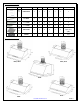
7. PARTS SUPPLIED PART SKETCH CODE DESCRIPTION PX10 PX11 PX12 UL10 UL11 UL13 DL09 M B MANUAL BOOK 1 1 1 1 1 1 1 OIL TUNNEL 1 1 1 1 1 1 1 1 ¾ “ SCREW 2 2 2 2 2 2 4 1 ¼ “ SCREW 4 4 4 4 4 4 4 B F BAFLE FILTERS 3 3 3 3 3 3 3 (36” / 42 “) 4 (48”) R C REMOTE CONTROL 1 N/A 1 N/A N/A N/A N/A O T S 1 S 2 8. HOOD DIMENSIONS PX11 / UL11 PX10 / UL10 DL09 UL13 PX12 www.XtremeAirUsa.
9. INSTALLATION NOTE: DO NOT TRY TO REMOVE BLOWER OR ITS HOUSING, YOU WON’T BE ABLE TO PUT IT BACK IN. MOREOVER, THE WARRANTY WILL BE VOIDED. STEP 1: PROTECT THE COOK TOP Put a thick, protective covering over counter top, cook top or range to protect from damage or dirt. STEP 2: CREATE WORK STATION (OPTIONAL) Have 2 pieces of wood about 2” x 4” x 20” on both sides of stove & a plywood on top of them to protect cook top or stove from damage or dirt.
STEP 7A: SECURE THE HOOD TO BOTTOM CABINET D09 model: please skip this step if you don’t have cabinet above the hood. From inside of the hood, use “hex bit extension” place 1 ¼” provided screw into each key hole (A) OR predrilled-holes (B) and secure to cabinet bottom. There are 8 holes (4 keyholes & 4 predrilled-holes) available. You can use either key or predrilled-hole as long as a minimum of 1 screw at each corner of hood body.
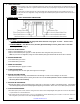
11. RANGE HOOD OPERATION IMPORTANT: BEFORE YOU BEGIN 1. For TOUCH SENSITIVE CONTROLS, please DO NOT PRESS. A light touch and hold on the required button for a matter of a (1) one second is all that is needed. CORRECT INCORRECT 2. TOUCH THE ENTIRE BUTTON: See illustration on right: For best results, Start the range hood before cooking and allow it to operate several minutes after the cooking is completed to clear all smoke and odors from the kitchen. VS. Entire button covered and lightly touched.
F. Remote Control Sensor: 1. Remote control sensor receives infrared (IR) signal from the remote control. The maximum distance for IR data transmission is 10 feet and requires direct line of sight. The transmission distance may vary depending on temperature and remote control battery condition. 2. Light settings are independent from other settings (including power-off delay) and lights have to be manually turned on or off. 3.
3. FOR ALL ULTRA SERIES: TYPE 3: MECHANICAL BUTTON CONTROL A. Activating Blower Function: Press your designed speed (1,2,3) B. Turn off power: While the blower (motor) is running, press button (0) to turn off the motors. C. To turn the light ON/OFF While the light is off, press button (4) once to turn on the light. Press button (4) again to turn the light off 4. FOR DL09 Model: TYPE 4: ELECTRONIC BUTTON CONTROL 12. SPECIFICATION A.
4. 5. 6. 7. Check that the duct sized used is at least 6”. Range hood WILL NOT function efficiently with insufficient duct size & loosely secured. Check if duct is clogged or if damper unit (half-circular flapper) is not installed correctly or opening properly. A tight mesh on a side wall cap unit might also cause restriction to the air flow. The lights work but the blower is not spinning at all, is stuck or is rattling. The blower might be jammed or scraping the bottom due to shipping damage.
16. LIMITED WARRANTY www.XtremeAirUsa.