
Use and Care Manual


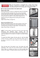

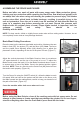


Table Of Contents

Do not plug this unit into a power source until assembly is complete.
To assemble the stand and motor, review the components diagram as shown in Figure 1 and
the Parts List on page 12. You may choose to begin assembling the stand first then add all
other components. The motor housing an be attached last. Once assembled, attach the rubber feet
to the four corners of the stand. The feet will help reduce vibration when the saw is in use.
NOTE: When installing the Motor Support Plate (Part # 82), it must angle toward the front,
otherwise the motor will not line up properly with the Drive Wheel in the upper housing. Ignore the
holes on top of Part # 95, as they serve no purpose. Once the stand and motor are assembled,
attach it to the main body of the saw using three long bolts, through the three elliptical openings (A)
in the Upper Cover (Part # 78).
Once the base is assembled, attach the Drive Belt (Part # 55) to
the motor wheel (A) and to the Spindle Wheel (B) in the
compartment directly above. If the two wheels don’t line up
properly, loosen the four bolts (C) holding the motor in place
and slide the motor up or down, depending on need. Once
the wheels line up, retighten the bolts. (Figure 2)