
Use and Care Manual


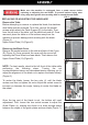

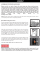


Table Of Contents

ASSEMBLING THE POWER SWITCH
Do not use sharp tools when assembling the power switch, as they
may damage the insulation on the wires. If you are unfamiliar with
electrical work, contact a professional electrician to perform the
install.
Use caution when guiding the table past
the saw blade as serious may occur.
Wear protective gloves.
Remove the four socket screws from the table support as described on
Page 7 (Figure 3). Then, from the left front side of the machine, hold the
table in both hands and guide it up onto the two table guide wheels (BB)
on that side. The wheels should fit the rails which are already attached to
the underside of the table. Guide the table across the top of the machine
to the guide wheels on the opposite side. Once the table is in place,
reattach the table support. (Figure 15)
The ON/OFF power switch is located in the upper corner of the stand.
Attach the switch to the side of the steel stand using two nuts, bolts and
washers. NOTE: Be sure ON is at the top. (Figure 12)
Take the single black power cord and insert the black, white and green
wires through the three parts of the cable bushing (AA) before inserting
them through the front panel of the stand. (Figure 13) Do not tighten the
bushing until the wires are connected to the proper terminals. Once the
wires are inserted through the front panel, insert them through one of the
holes in the switch cover. (The cover has been removed in Figure 13 to
better show the connections to the terminals.) Be sure the clear plastic
insulation stays with each wire. Once the wires are through, pull some of
the black cable through as well. This will make it easier to connect the
wires to the terminals.
Insert the black, white and green wires coming off the motor into the other
hole inthe switch cover.
Attach the black wires to the terminals on one side of the switch, and the
white wires to the terminals on the other side. The green Ground wires are
connected directly to the steel side panel with a nut, bolt and washer on
each. The Ground symbol is located in the center of two holes, which are
covered by stickers. Remove the stickers, insert a bolt with the ground wire
attached through each, and apply the washer and nut. Once tightened, the
Ground wires use the steel structure of the machine to ground the electric.
(Figure 13)
Attach the switch cover (Z) to the steel cabinet with nuts, bolts and
washers, and tighten the cable bushing (AA) by hand. (Figure 14)
Attaching the Stainless Steel Table
Figure 12