GAS LOG SPLITTER 196CC / 6.5HP ITEM# 65068 / 65069 GAS LOG SPLITTER 277CC / 9.0HP ITEM# 65070 OWNER’S MANUAL AND SAFETY INSTRUCTIONS SAVE THIS MANUAL. KEEP THIS MANUAL FOR SAFETY WARNINGS, PRECAUTIONS, ASSEMBLY, OPERATION, INSPECTION, MAINTENANCE AND CLEANING PROCEDURES. WRITE THE PRODUCT’S SERIAL NUMBER ON THE BACK OF THE MANUAL, OR THE MONTH AND YEAR OF PURCHASE IF PRODUCT HAS NO SERIAL NUMBER. FOR QUESTIONS, PLEASE CALL CUSTOMER SERVICE: 909.628.
TABLE OF CONTENTS GB INTRODUCTION TABLE OF CONTENTS Introduction 2 Specifications 2 Environmental 3 Symbols 3 Safety 5 General Safety Rules 5 Specific Safety Rules 7 Contents Supplied 9 Assembly 11 Your new Gas Log Splitter will more than satisfy your expectations. It has been manufactured under stringent quality standards to meet superior performance criteria. You will find it easy and safe to operate, and with proper care, it will give you many years of dependable service.
SAFETY WARNINGS Pump Size Hydraulic Cylinder Bore 2-stage 13/1.8 GPM 2-stage 13/1.8 GPM 2-stage 15/3.0 GPM 4" 4.5" 5" Hydraulic Cylinder Stroke 24" Hydraulic Rod Diameter 1.75" 2" Cylinder Cycle Time* 11.2 seconds 12.9 seconds 12.7 seconds Hydraulic Oil Required to Fill 4.49 Gallon 4.75 Gallon 6.34 Gallon Hydraulic Oil Included Not Included Replacement Filters Built-in Filter Beam Heavy duty H-shape formed construction Wedge Size 7" 8" Wedge Style 2-way Rear Wheels 4.
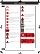
SAFETY WARNINGS GB Wear protective gloves. Keep hands away from moving parts. Moving parts can crush or cut. Wear safety footwear. Keep feet away from moving parts. Moving parts can crush or cut. Do not remove or tamper with the protection and safety devices. Always keep body and hands away from pin holes or nozzles that eject hydraulic fluid under pressure. Escaping hydraulic fluid can puncture skin and cause blood poisoning. Don’t stand or sit on the log splitter.
SAFETY WARNINGS SAFETY General Safety Rules Understand Your Machine Read this manual and labels affixed to the machine to understand its limitations and potential hazards. Be thoroughly familiar with the controls and their proper operation. Know how to stop the machine and disengage the controls quickly. Make sure to read and understand all the instructions and safety precautions as outlined in the Engine Manufacturer’s manual packed separately with your unit.
SAFETY WARNINGS GB Avoid accidental starting. Be sure the engine’s switch is off before transporting the machine or performing any maintenance or service on the unit. Transporting or performing maintenance or service on a machine with its switch on invites accidents. If the machine should start to vibrate abnormally, stop the engine (motor) and check immediately for the cause. Vibration is generally a warning sign of trouble. Engine Safety This machine is equipped with an internal combustion engine.
SAFETY WARNINGS Hydraulic fluid can result in severe burns. Fluid in the hydraulic system can penetrate skin and result in serious injury or death. Be sure to stop the engine and relieve hydraulic pressure before doing any work on hydraulic parts. Keep body and hands away from pin holes or nozzles that expel hydraulic fluid when under pressure. Use paper or cardboard, not hands, to search for leaks.
SAFETY WARNINGS GB Machine Use And Care Never operate the machine without good visibility or light. Never attempt to split wood across the grain. The log splitter was not designed for crossgrain splitting. Always block the front and back of both wheels to prevent unintended movement. Hold the bark side of the logs when loading or positioning, never the ends. Never place your hands or any part of your body between a log and any part of the log splitter.
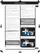
ASSEMBLY UNPACKING THE CONTAINER GB 1. Remove plastic wrap on crate. 2. Remove restraining bolts (tee nut bolts) from the beam. Use a 13mm wrench or socket to remove the two hex bolts that are securing the beam to the crate bottom (as shown below). Please note that the two hex bolts are located diagonally opposed to each other. 5. Use a 13mm wrench or socket to remove the two hex bolts that secure the engine to the crate bottom (as shown below). 3.
ASSEMBLY CONTENTS SUPPLIED GB Your log splitter comes partially assembled and contains the following: Heavy lifting required. Some of the components in these assembly instructions are heavy and can't be lifted by one person safely. Please plan to assemble this product when another person can be available to help. 3 6 9 10 5 1 4 2 7 8 11 1. Tank & Engine 11. Hardware Kit, Including: 2. Tongue & Stand 3. Beam & Cylinder 4. Wheel/Tire 5. Beam Lock Bracket 6.
M8×45 (×4) ASSEMBLY ASSEMBLY This log splitter was partially assembled at the factory. To assemble your machine follow the below instructions. 2. P lace Engine on tank. Secure Engine on Tank in 4 places with Hex Bolt, M8×45mm, Flat Washer, M8 and Hex Nut, Locking nut, M8. GB Engine 1. Remove Engine Bolts from tank.
ASSEMBLY GB Wheels 1. Remove disposable spindle covers and wheel bearing covers. Installation of the cotter pin is important and required. Failure to install the cotter pin can result in loss of wheel retention. Always assemble using a new cotter pin. Do not reuse. Tank & Tongue 1. Attach the Tongue & Stand to the Tank & Engine with Hex Bolt M12×110 mm, Flat Washer, Lock Washer and Hex Nut in two places. Tighten securely using 19mm socket wrenches. 2.
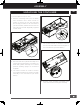
ASSEMBLY Beam Bracket Beam To Reservoir 1. Attach the Beam Lock Bracket to the Beam & Cylinder with Hex Bolt, Flat Washer, Lock Washer and Hex Nut in two places. Tighten securely using 19mm socket wrenches. GB 1. R otate the Stand attached to the side of the Tongue downwards into position by releasing the pin and then securing the release pin. 2. R emove the Retaining Clip and Hitch Pin from the assembled unit (as shown below). Slowly back the assembled unit up to the Beam & Cylinder.
ASSEMBLY GB Hydraulic Line Connection 1. A ttach suction line tube to pump. Fasten the suction line tube to the pump assembly with hose clamp. 2. A pply teflon tape or pipe sealant on to the hose fitting threads. Install the ends of the two hydraulic hoses to the valve, pump/ tank(as shown in detail drawing). Securely tighten the fitting connections using 27mm and 32 mm wrenches. Log Catcher 1. A lign holes in log catcher with holes in the beam. 2.
OPERATION KNOW YOUR MACHINE GB Features and Controls Foot Plate Beam Assembly Log Catcher Log Stripper Split Control Handle Cylinder Beam Lock Bracket Lifting Handle Manual Canister 2" Ball Hitch Coupler Tank 15
OPERATION GB Engine On/Off Switch Recoil Starter Handle Throttle Control Choke Control Fuel Shut-Off Valve Split Control Handle Beam Lock Bracket The control handle is used to move the wedge up and down to split logs. The control handle has three positions: Forward, Neutral, and Reverse. See the “operation” section for instruction. Pull outward the lock pin and lift up the lifting handle to transit the beam position from horizontal to vertical. Keep manuals safely in the canister.
OPERATION Operation IMPORTANT: DO NOT OVERFILL! Many accidents occur when more than one person operates the log splitter. If a helper is assisting in loading logs to be split, never operate the controls until the helper is clear of the area. Always check oil level before starting the engine and keep level full. Add Oil To Engine 1. M ake sure the log splitter is on a flat, level surface. 2. R emove the oil fill cap/dipstick to add oil. OPEN CLOSED 3.
OPERATION GB HYDRAULIC OIL FILLING Oil Tank Cap MAX. 5. M ove the throttle lever slightly to the FAST speed. FAST SLOW MIN. 6. 4. M ake sure the hydraulic oil level reaches the upper line of the dipstick. Completely install the dipstick when checking oil level. 5. S tart the engine and use the control valve handle to extend and retract the wedge five times to remove air from the high pressure lines. 6. W ith the wedge retracted and engine off, check the oil level again. Fill if necessary. 7.
OPERATION Cracks in logs can close quickly and pinch fingers. Keep fingers away from any cracks that open in partially split logs. Do not use the unit if the stripper plates are bent or damaged. Bent or damaged stripper plates must be repaired or replaced before use. GB Neutral position – In this position the cylinder does not move even though the engine is running. Reverse position – Move the lever in this position to retract the cylinder. Push the lever fully in this direction to lock it return mode.
OPERATION GB TRANSPORTING Moving By Hands The log splitter is heavy. It can crush and cause serious injury if it rolls out of control or tips over. Follow the instructions below for safely moving the log splitter. 1. M ake sure the log splitter is locked in the horizontal position with latch rod before moving. Make sure the log splitter engine is off. Never move the log splitter with its engine running. 2. T urn the fuel shut-off valve to the OFF position.
MAINTENANCE Drive slowly and take extra caution when traveling over rough terrain. If towing on a public road, make sure to comply with all local, state, and federal towing requirements. It is the sole responsibility of the purchaser to obtain licensing, trailer lights, safety chains, or signage as needed to comply. Oil Draining GB Use a drain pan to aid in the removal of all used oil and particles. 1. Disconnect the suction line tube from the pump by loosing the hose clamp.
MAINTENANCE GB STORAGE Follow the instructions below for storing your log splitter between uses. 1. R etract the wedge completely to keep the rod protected from corrosion. 2. A llow the machine to cool 5 minutes before storing. 3. C lear the debris from the beam, wedge, and end plate. Use a damp cloth to clear exterior surfaces of the engine and log splitter. Use a soft bristle brush to remove excess dirt and oil. Use an air compressor (25 PSI) to clear dirt and small debris.
TROUBLE SHOOTING TROUBLE SHOOTING Problem Cause 1. Air in the hydraulic oil system Wedge movement 2. Debris lodged in beam guides is slow or erratic 3. Low hydraulic oil GB Remedy 1. P urge air by extending and retracting the wedge several times until motion is smooth 2. Clear debris from beam 3. Check oil level and add as needed 1.
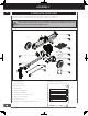
PARTS INFORMATION PARTS SCHEDULE GB 10 7 6 11 12 OPTIONAL 9 13 5 4 14 3 15 19 2 1 80 11 28 81 80 81 33 11 10 29 30 32 31 23 22 50 51 56 57 55 52 53 54 61 47 36 35 58 59 60 42 23 34 48 49 62 42 23 64 65 27 39 40 23 67 46 70 71 45 63 72 69 32 66 41 68 20 68 20 73 74 75 76 78 77 24 79
PARTS INFORMATION 65068 / 65069 Parts List No. Description Q'ty No. Description GB Q'ty 1 Clevis Pin Assy 1 41 Oil Return Line Tube 2 Cylinder 1 42 Lock Washer, M8 12 3 Elbow Fitting 1 2 43 4 Tube 1 44 5 Fitting 1 45 Hex Bolt, M8×40 4 6 Valve Assembly 1 46 Tank 1 7 Elbow Fitting 2 1 47 Vent Cap 1 48 R-Clip 1 8 1 9 Nipple 1/2 NPT 1 49 Hitch Pin 1 10 Hex Nut M12×1.75 5 50 Hex Bolt, M8×20 4 11 Lock Washer, M12 8 51 Pump 1 12 Wedge, 8-in.
PARTS INFORMATION 65070 Parts List GB No. Description Q'ty No. Q'ty 1 Clevis Pin Assy 1 41 Oil Return Line Tube 2 Cylinder 1 42 Lock Washer, M8 12 3 Elbow Fitting 1 2 43 4 Tube 1 44 5 Fitting 1 45 Hex Bolt, M10×45 4 6 Valve Assembly 1 46 Tank 1 7 Elbow Fitting 2 1 47 Vent Cap 1 48 R-Clip 1 8 26 Description 1 9 Nipple 1/2 NPT 1 49 Hitch Pin 1 10 Hex Nut M12×1.75 5 50 Hex Bolt, M8×20 4 11 Lock Washer, M12 8 51 Pump 1 12 Wedge, 8-in.
PARTS INFORMATION GB 27
OF NOTE PLEASE READ THE FLOLLOWING CAREFULLY THE MANUFACTURER AND/OR DISTRIBUTOR HAS PROVIDED THE PARTS LIST AND ASSEMBLY DIAGRAM IN THIS MANUAL AS A REFERENCE TOO ONLY. NEITHER THE MANUFACTURER OR DISTRIBUTOR MAKES ANY REPRESENTATION OR WARRANTY OF ANY KIND TO THE BUYER THAT HE OR SHE IS QUALIFIED TO MAKE ANY REPAIRS TO THE PRODUCT, OR THAT HE OR SHE IS QUALIFIED TO REPLACE ANY PARTS OF THE PRODUCT.