
Specifications

COPYRIGHT ©2019 ALL RIGHTS RESERVED Xun Tong Tech TEL: + 86 75526675941 E-mail: nrf@freqchina.com
4
mode.
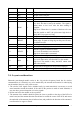
2 TX O TX pin of the serial port.
3 RX I RX pin of the serial port.
4 SWDIO / /
5 SWCLK / /
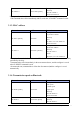
6 DON O
Indicative signal of data output.
Low level: No data is sent by the module . The signal is
pulled down to low level after the data sending is
complete.
High level: When there is a stream of data has to be sent
from the module to MCU, the pin become high level to
notify MCU to prepare receiving.
7 GPIO3 I/O This pin can be configured as an input or output pin.
8 RESET I
Module reset pin
Rising edge: A signal of rising edge on this pin will cause
the module to reset.
9 GND / Module ground pin
10 VCC / Module power supply positive 1.8 ~ 3.6 V
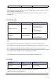
11 STATE O
Indicative signal of connection status
Low level: the module is not connected
High level: the module is connected
12 GPIO0 I/O This pin can be configured as an input and output pin.
13 DIN O
Indicative signal of data input:
Low level: Data can be sent from MCU to the module.
High level: The module is busy, the MCU cannot send
data to the module.
14 GPIO1 I/O The pin can be configured as an input and output pin.
15 GPIO2 I/O The pin can be configured as an input and output pin.
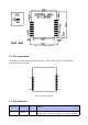
Table 1 Pin Definition
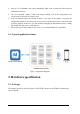
2.4. Layout considerations
Bluetooth pass-through module works in the 2.4g wireless frequency band, but for wireless
communication, it is relatively easy to be interfered by the external environment. So when laying
out the module, there are a few points to note:
1. The wireless 2.4G signals can be shielded easily by metal materials,it is necessary to avoid
metal materials around the module. If the shell of the product is made of metal materials, it
may also have greater absorption of wireless signals.
2. Do not rout below the module as far as possible.
3. The antenna of the module should be placed as close as possible to the edge of the PCB of a
main board, and the antenna direction should not be toward the center of the PCB, and ensure
the underside of the antenna plate is hollowed out, and parallel to the direction of the antenna is
not allowed to be copper or traced.