X100 SERIES User Manual
X100 Series Main User Manual RECORDING SOFTWARE CONFIGURE SETUP INSTALL & CONNECT QUICK GUIDE CONTENTS INTRODUCTION.................................................................................................... 5 i Overview ............................................................................................................ 5 ii Features ............................................................................................................. 5 Standard Features across the Range ..
X100 Series Main User Manual 74 76 77 78 82 86 CONFIGURE RECORDING SOFTWARE 4.10 PTZ Control ............................................................................................................................ 118 4.11 Alarm Setting ........................................................................................................................ 119 4.11.1 Setting/Adding and Event .............................................................................................. 119 4.11.
RECORDING SOFTWARE CONFIGURE SETUP INSTALL & CONNECT 4 X100 Series Main User Manual - PLAYBACK 4.13 Playback Interface ................................................................................................... 128 4.14 Search Recorded Files ............................................................................................. 129 4.15 Convert to AVI Files ................................................................................................ 131 4.16 Audio Modes ..............
X100 Series Main User Manual 5 i OVERVIEW ii FEATURES STANDARD FEATURES ACROSS THE X100 IP CAMERA RANGE INSTALL & CONNECT This user guide explains how to operate your camera from a computer. Please ensure you read this manual before attempting to operate the device. • Easy ‘Plug and Play’ installation and configuration using the Setup Wizard • 1.3 Megapixel High Definition images up to 1280x1024 resolution, 3x the resolution of standard CCTV cameras • IEEE 802.
X100 Series Main User Manual RECORDING SOFTWARE CONFIGURE SETUP INSTALL & CONNECT ADDITIONAL FEATURES X100C WIRELESS IP CUBE CAMERA • White LEDs for 10m Night Vision • 4.0mm Lens for 50° viewing angle • SD Card Recording • Designed for Wall, Ceiling or Desk mounting • Suitable for indoor use only X104P WIRELESS PAN TILT ZOOM IP CAMERA • White LEDs for 10m Night Vision • 4.
X100 Series Main User Manual 7 iii MINIMUM SYSTEM REQUIREMENTS The following are the minimum system requirements for the X100 Series IP Camera Range: Wired Models Wireless Model (X100C, X104P) Network Interface: 10/100MBase-TX Ethernet 10/100MBase-TX Ethernet 802.11b/g or n WLAN Browser: Internet Explorer 6.0, Safari 5.0, FireFox 3.5 or later System Hardware CPU: Pentium 4, 2.
X100 Series Main User Manual 8 RECORDING SOFTWARE CONFIGURE SETUP INSTALL & CONNECT iv NOTES ON INSTALLATION • Please unpack all boxes carefully and identify that all the parts are present. • Do not aim the camera at the sun or similar intense light. • Treat the camera with care. • Do not open the camera to make internal adjustments unless instructed to do so in this manual.
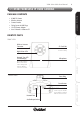
X100 Series Main User Manual 9 1.1 X100C WIRELESS IP CUBE CAMERA PACKAGE CONTENTS INSTALL & CONNECT • • • • • • X100C IP Camera Wireless Antenna Camera Bracket Fixing Screws & Wall Plugs 12V DC Power Adaptor User’s Manual & Software CD IDENTIFY PARTS FRONT VIEW Night Vision LEDs Network Type LED (Green/Orange) SD Card Slot Insert SD Card for on board recording Microphone CONFIGURE Green LED indicates Wired connection is active. Orange LED indicates Wireless connection is active.
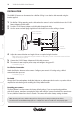
X100 Series Main User Manual INSTALL & CONNECT INSTALLATION The X100C IP Camera can be mounted on a Wall or Ceiling. It can also be desk mounted using the bracket supplied. 1. 2. 3. For Wall or Ceiling mounting, make a hole where the camera is to be installed to insert the 12V DC Power Adaptor and LAN cable. Feed the 12V DC Power Adaptor, and LAN cables through the hole. Use the screws and wall plugs supplied to fix the bracket on a wall or ceiling as shown.
X100 Series Main User Manual 11 1.2 X10⁴P WIRELESS PAN TILT ZOOM IP CAMERA PACKAGE CONTENTS • Fixing Screws & Wall Plugs • 12V DC Power Adaptor • User’s Manual & Software CD IDENTIFY PARTS INSTALL & CONNECT • X104P IP Camera • Wireless Antenna • L-Bracket with 2x Screws FRONT VIEW Lens Camera Body Focus Ring Night Vision LEDs Lens Mechanism Network Type LEDs (Green/Orange) The Lens Mechanism can tilt (up & down) 100°. Green LED indicates Wired connection is active.
X100 Series Main User Manual The X104P IP Camera can be mounted on a Wall or Ceiling using the L-Bracket provided. It is designed for internal use only. It can also be desk mounted as supplied. 1. 2. 3. For Wall or Ceiling mounting, make a hole where the camera is to be installed to insert the 12V DC Power Adaptor and LAN cable. Feed the 12V DC Power Adaptor and LAN cables through the hole. Use the screws and wall plugs supplied to fix the bracket to the camera, then to the ceiling as shown.
X100 Series Main User Manual 13 Note: Restoring the factory default setting will lose all the previous settings including the IP address. You will need to run the IPWizard II program to re-configure the camera to enable it to work properly again. INSTALL & CONNECT Resetting your camera The Reset Button is used to restore the factory default settings. If you are experiencing problems with the IP camera, sometimes restarting the device will make the system revert back to a normal state.
X100 Series Main User Manual 1.
X100 Series Main User Manual 15 INSTALLATION 2. 3. 4. 5. Select a mounting position on a wall or ceiling. Rotate the dome housing anti-clockwise to remove the camera from the mounting base. Use the mounting base to mark up screw positions and make a hole in the wall or ceiling to insert the LAN cable and 12V DC Cable (if using Power over Ethernet, 12V DC Power is not required). Feed the cables through the hole. Use the screws and wall plugs supplied to fix the mounting base.
6. X100 Series Main User Manual Adjust the camera direction and angle of view as required using the camera bracket inside. INSTALL & CONNECT -- Make any lens (focus) adjustments using the manual Focus Ring after you have connected the camera and have setup live viewing via your PC. CAMERA DIRECTION ADJUSTMENT Camera bracket For Horizontal Adjustment Camera’s Tilt bracket For Vertical Angle Adjustment SETUP Camera’s Board hinge For Horizontal (Left/Right) Board Adjustment Focus Ring 7.
X100 Series Main User Manual 17 Place spring on new lens before screwing back on to board mount For Audio Connect an external Microphone for monitoring audio. Connect an audio output device such as a speaker with an amplifier for voice alerting or for enabling the 2 Way Audio function. See table below for details on connection. SETUP Note: The following Xvision Megapixel lenses are compatible with the X100D IP camera: • XL010P-PRO (1.
X100 Series Main User Manual 18 1.
X100 Series Main User Manual 19 INSTALLATION 2. 3. 4. 5. Select a mounting position on a wall or ceiling. Decide whether the cables are to go through the dome base or via the side cable exit and block off the unused exit with the stopper. Remove the dome housing by unscrewing the tamper resistant screws with an Allen Key.
INSTALL & CONNECT 7. X100 Series Main User Manual Adjust the camera direction and angle of view as required using the camera bracket inside. -- Make any lens (Zoom/Focus) adjustments after you have connected the camera & have setup live viewing via your PC. -- Make the Zoom Adjustment by rotating the screw anticlockwise for NEAR adjustment and clockwise for FAR adjustment until you get the desired view.
X100 Series Main User Manual 8. 21 Connect the 12V DC Power Adaptor to the Power Cable and attach the positive (+) to VCC12 and the negative (-) to GND as shown (if using POE this step is not required): Power Adaptor (to Mains Power) - Power Cable VCC12 GND DIGITAL_IN ALARM_OUT AUDIO_IN AUDIO_OUT AUDIO_GND INSTALL & CONNECT + Note: Incorrect wiring may cause damage to the camera. Please ensure + and - terminal connections are fitted correctly. SETUP 9.
INSTALL & CONNECT 22 X100 Series Main User Manual Resetting your camera The Reset Button is used to restore the factory default settings. If you are experiencing problems with the IP camera, sometimes restarting the device will make the system revert back to a normal state. To reset, hold the button for at least 5 seconds. The camera will restore factory settings & reboot. Note: Restoring the factory default setting will lose all the previous settings including the IP address.
X100 Series Main User Manual 23 1.
X100 Series Main User Manual 1. 2. Select a mounting position and make a hole where the camera is to be installed Use the screws and wall plugs supplied to fix the bracket on a wall or ceiling as shown. WALL MOUNT Feed trailing lead through wall CEILING MOUNT Feed trailing lead through ceiling Slide forward sun/rain shield to fix bracket to camera RECORDING SOFTWARE CONFIGURE SETUP INSTALL & CONNECT INSTALLATION 3. 4. 5. 6. Feed the trailing lead with connections through the hole.
X100 Series Main User Manual 25 Alarm and RS485 Connections ALARM SENSOR (Optional) RS485 Cable Name (Colour) Connect to: DI (Green/White) Alarm Sensor Input DO (Orange/White) Alarm Output 12V DC (Brown/White) Alarm Output Power (12V DC 50mA Max) GND (Blue/White) Alarm Sensor Ground RS485 + (Purple/White) Not used RS485 - (Grey) Not used Note: Restoring the factory default setting will lose all the previous settings including the IP address.
X100 Series Main User Manual 26 1.
X100 Series Main User Manual 27 INSTALLATION 2. 3. Select a mounting position on a wall or ceiling. Make a hole where the camera is to be installed to insert the LAN cable and 12V DC Cable (if using Power over Ethernet, 12V DC Power is not required). Feed the cables through the hole. Use the screws and wall plugs supplied to fix the bracket on a wall or ceiling as shown. WALL MOUNT INSTALL & CONNECT 1. To Power To Network SETUP Focus Ring CEILING MOUNT CONFIGURE To Network To Power 4.
INSTALL & CONNECT 5. 6. X100 Series Main User Manual Connect the LAN cable and 12V DC Power Adaptor to camera. The camera is now ready for you to setup and configure your camera using your PC. -- See SETUP on page 36. Using an Optional Lens The X100T camera is supplied with a 4.0mm fixed lens for 50° viewing angle. The lens can be manually replaced with an Xvision Megapixel Varifocal or Fixed Lens to achieve a different viewing angle.
X100 Series Main User Manual 29 *Calibration required, see page 61. INSTALL & CONNECT Note: The following Xvision Megapixel lenses are compatible with the X100T IP camera: • XL010M-PRO (1.55mm Fixed Iris Megapixel Lens, for 135° viewing angle) • XL040M-PRO (4.0mm Fixed Iris Megapixel Lens, for 64° viewing angle) • XL0550M-PRO (5.0 to 50.0mm Manual Iris Varifocal Megapixel Lens, for 6 to 49° viewing angle) • XL0409A-PRO (4.0 to 9.
X100 Series Main User Manual 1.7 X10⁴S VANDAL RESISTANT IP SPEED DOME INSTALL & CONNECT PACKAGE CONTENTS • X104S IP Camera • Ceiling Mount with 4x Screws • Fixing Screws & Wall Plugs • Allen Key • 12V DC Power Adaptor • User’s Manual & Software CD IDENTIFY PARTS SIDE VIEW Ceiling Mount SETUP Fixing Slot for mounting camera Trailing Lead Speed Dome Housing Note: An optional Wall mount bracket is available Speed Dome Cover for mounting the camera against a wall.
X100 Series Main User Manual 31 INSTALLATION Make a hole in the ceiling where the camera is to be installed. Use the screws and wall plugs supplied to fix the bracket on the ceiling. INSTALL & CONNECT 1. 2. Hole to feed trailing lead through the ceiling Feed the trailing lead through the Ceiling Mount and fix the camera to the bracket as shown: SETUP 3. Screw Dome Housing to Ceiling Mount using the Allen Key provided 4. -- See SETUP on page 36. Fitting the optional Wall Bracket 1.
X100 Series Main User Manual INSTALL & CONNECT 4 CAMERA INSTALLATION Lens Adjustment Make any lens (focus) adjustments after you have connected the camera and have setup live viewing via your PC. To adjust the lens, open the Dome Cover by turning it anti-clockwise and rotate the Focus Ring. Focus Ring For Audio Connect the 3.5mm microphone Audio In Socket to an external Microphone for audio monitoring. Connect the 3.
X100 Series Main User Manual 33 1.8 X100VS VIDEO SERVER (CODEC) PACKAGE CONTENTS IDENTIFY PARTS FRONT VIEW Network Port INSTALL & CONNECT • Audio/Video Output Cable • Power Cable for External Camera • User’s Manual & Software CD • X100VS Video Server • 12V DC Power Adaptor • User’s Manual & Software CD 12V DC Out Power Socket Alarm I/O connections 12V DC OUT SETUP LAN DI/DO/ RS485 VIDEO IN Power Cable for External Camera BNC Video Input (optional) Used to power one camera. 12V DC 400mA Max.
X100 Series Main User Manual INSTALL & CONNECT INSTALLATION 1. 2. Attach Video lead from your analogue camera to the BNC Video Input -- Ensure the analogue camera is powered Connect the LAN cable and 12V DC Cable to the Video Server (if using Power over Ethernet, 12V DC Power is not required). To Network To Mains Power (not required if Power over Ethernet being used) VIDEO SERVER From analogue camera SETUP 3. The unit is now ready for you to setup and configure using your PC.
X100 Series Main User Manual 35 The protocols supported are: -- Pelco D -- Pelco P SETUP Resetting your camera The Reset Button is used to restore the factory default settings. If you are experiencing problems with the IP camera, sometimes restarting the device will make the system revert back to a normal state. To reset, hold the button for at least 5 seconds. The camera will restore factory settings & reboot.
X100 Series Main User Manual 36 2.1 SETTING UP YOUR NETWORK INSTALL & CONNECT WHAT YOU NEED 1. 2. 3. Your X100 Series IP Camera(s) LAN cable and Connection Equipment such as a hub or router suitable for your network environment -- Use Cat5 STRAIGHT THROUGH cable to connect the IP Camera(s) to a network switch or hub. -- For more information on Connection Configuration, see Appendix A. An ‘Administrator’ PC/Laptop running Internet Explorer 6.
X100 Series Main User Manual 37 2.2 SEARCH AND SETUP USING IPWIZARD II SETTING UP THE IPWIZARD II ON YOUR PC Locate the IPWizard II Installer file inside the IPWizard II folder on the User Manual CD Double click the file and follow the on screen instructions to install the software. -- An application shortcut icon will be placed on your PC’s desktop, double click to launch the software. INSTALL & CONNECT 1. 2. USING THE IPWIZARD II TO SEARCH FOR YOUR IP CAMERA Launch the software. Click SEARCH.
X100 Series Main User Manual 38 5. Click LAN to configure your IP camera with your network settings. -- There are 2 options to set the IP address; Static IP or DHCP IP. Your option depends on how your network is setup. Speak with your System Administrator or see the information box below for more information. -- When entering the IP address manually, select the STATIC IP option and enter the IP address, Subnet Mask, Gateway, primary DNS and secondary DNS.
X100 Series Main User Manual 6. 39 -- To Change the User Name and Password, tick the box and enter your User Name and Password as required -- To go back to the previous window without saving any changes, click -- To save all the details, click INSTALL & CONNECT On the next page in the LAN menu, configure your User Name and Password. (We recommend that the default User Name and Passwords are left as they are until your camera has been configured. The password security can be set up and changed later).
An information window will appear. Confirm your settings by clicking OK. SETUP INSTALL & CONNECT 8. X100 Series Main User Manual -- To change any details, click CANCEL and edit the information in the WIRELESS menu. RECORDING SOFTWARE CONFIGURE 9. The IPWizard II will begin configuring the camera to your specifications then prompt you to unplug the Ethernet cable to activate the wireless settings. Follow the on-screen instructions to TEST your wireless settings.
X100 Series Main User Manual 41 EXIT IPWIZARD II Camera’s web configuration page where you can adjust the camera settings. INSTALL & CONNECT 10. When you have finished, click EXIT to quit the program. You are now ready to access your IP SETUP See the following pages for alternative methods to search and setup your camera (instead of using IP Wizard II).
X100 Series Main User Manual 42 2.3 SEARCH AND SETUP USING WINDOWS UPnP INSTALL & CONNECT WHAT IS UPnP? UPnP™ is short for Universal Plug and Play, which is a networking architecture that provides compatibility among networking equipment, software, and other peripherals. The X100 IP range of cameras and video server are UPnP enabled devices. If your PC Windows XP or Vista operating system is UPnP enabled, the IP Camera will be very easy to locate on the network.
X100 Series Main User Manual 43 2.4 SETUP BEHIND A NAT ROUTER WHAT IS NAT? Once you have installed your IP camera it will be accessible on your Local Area Network (LAN). To access the camera from the Internet you must configure your broadband router to allow incoming data traffic to the device. If the camera is installed on the LAN with a router, then it may get a dynamic IP address from the DHCP server.
X100 Series Main User Manual 44 SETUP INSTALL & CONNECT 2.5 ACCESS YOUR CAMERA USING YOUR WEB BROWSER 1. 2. Open your web browser Type in your camera’s IP address in the format: http://192.168.0.100 -- If you have set up your own IP address, replace 192.168.0.100 with the new address. -- The Login Window of the IP Camera will pop up as shown. 3.
X100 Series Main User Manual 45 3.1 WEB BROWSER INTERFACE When you login, either as an Administrator or as a general User, the start-up screen will be as shown: Active X Button See overleaf for details Image Screen The date and time are displayed at the top. INSTALL & CONNECT MAIN SCREEN Status Bar The camera supports either megapixel or multi profile modes for both MEPG4 and JPEG simultaneously. Choose the preferred profile listed here.
X100 Series Main User Manual 3.2 ACTIVE X CONTROLS INSTALL & CONNECT Press the Active X button on the top right side of the interface to access the Active X Menu. Active X Button SETUP DIGITAL ZOOM Drag or scale the box over the video to adjust zoom ratio and position as shown: CONFIGURE Scale and move the windowed area to set the zoom and position on screen RECORD Press the RECORD button to start recording. The video file will be saved as ASF format on your PC. Press Stop to stop recording.
X100 Series Main User Manual 47 SNAPSHOT Saved images can be opened in your default image application. INSTALL & CONNECT Press the SNAPSHOT button to take a picture. The image file will be saved as JPEG format on your PC. Select BROWSER to save the file in a selected folder, click OK to continue. VOICE CONFIGURE STATISTICS SETUP The VOICE function allows you to control the speaker and microphone levels of the camera. There are two control bars for speaker and microphone volume respectively.
X100 Series Main User Manual RECORDING SOFTWARE CONFIGURE SETUP INSTALL & CONNECT ABOUT Click ABOUT to show camera information.
X100 Series Main User Manual 49 3.3 MAIN SETTINGS MENU Note: The Main Settings Menu is only available for user logged into the camera as an Administrator.
X100 Series Main User Manual 3.4 NETWORK MENU SETUP INSTALL & CONNECT NETWORK TAB This section provides the menu for connecting the device through Ethernet cable. MAC address Displays the Ethernet MAC address of the device. (This cannot be changed). CONFIGURE Obtain IP address automatically (DHCP) (Dynamic Host Configuration Protocol) Check this box when a DHCP server is installed on the network to issue IP address assignment. With this setting, the IP address is assigned automatically.
X100 Series Main User Manual 51 http://xx.xx.xx.xx/ or http://xx.xx.xx.xx:xxxx/ to access the IP camera. -- If multiple IP cameras are installed on the LAN and are also required to be accessed from the WAN, then the HTTP Port can be assigned as the virtual server port mapping to support multiple devices. WIRELESS TAB for X100C and X104P Wireless IP Cameras -- Using a wired connection ensures greater secrecy while making changes. -- You will need your Wireless Network and Security settings for this.
Select your security mode (WEP or WPA). Then click the SUBMIT button to activate the settings. INSTALL & CONNECT 2. X100 Series Main User Manual CONFIGURE SETUP To configure the Wireless Settings manually use the following fields: Use the TEST button to test the wireless settings before saving any changes. MAC address Displays the Ethernet MAC address of the WLAN card. This cannot be changed.
X100 Series Main User Manual 53 BSSID (Basic Service Set Identifier) Related to SSID, BSSID refers to the MAC address of the Station (STA) in an Access Point (AP). Security mode Select which type of security the network uses. The device supports three security methods: NONE, WEP or WPA_PSK/WPA2_PSK. You will need to know your wireless network security settings to complete this section. INSTALL & CONNECT Channel Chooses the wireless channel in the wireless network.
X100 Series Main User Manual www.DynDNS.org. You’ll need to register with the service and set up the domain name of your choice to begin using it. Please refer to the home page of the service for detailed instructions or refer to Appendix D for more information. -- If your camera is connected to xDSL directly, you might need this feature as most of the users will use dynamic IP addresses. If users want to set up a web or a FTP server, then the Dynamic Domain Name Server is necessary.
X100 Series Main User Manual 55 PPPoE TAB PPPoE is a network protocol that allows data communication between two network points. It allows the IP camera to connect to xDSL or cable broadband network directly and automatically assign itself a dynamic IP address. For more details on PPPoE and Internet configuration, please consult your ISP. The IP camera’s PPPoE information should be setup in a LAN environment to setup before connecting to the xDSL modem.
X100 Series Main User Manual RTSP (Real Time Streaming Protocol) is a streaming control protocol used to establish and control multimedia streams. RTSP can be considered a ‘remote control’ for controlling the media stream delivered by a media server. RTSP servers typically use RTP as the protocol for the actual transport of audio/video data. SETUP INSTALL & CONNECT STREAMING TAB RECORDING SOFTWARE CONFIGURE RTSP Port Choose the RTSP port.
X100 Series Main User Manual 57 INSTALL & CONNECT UPnP Enable or disable the UPnP service using the toggle buttons. SETUP Friendly Name Shows the friendly name of this device here. UPnP NAT Traversal When enabled, the camera will attempt to configure port mapping in a NAT router on your network, using UPnP™. Note that UPnP™ must be enabled in the NAT router first. Port Range The port range will open in NAT router.
X100 Series Main User Manual INSTALL & CONNECT BONJOUR TAB The X100 IP range of cameras and video server also support the Bonjour protocol. If your network environment uses this, then it can be enabled using this menu. SETUP Bonjour Enable or disable the Bonjour service using the toggle buttons. Friendly Name (read only) Shows the Name assigned to the IP camera.
X100 Series Main User Manual 59 IP NOTIFICATION TAB INSTALL & CONNECT If the IP address of the camera changes, the IP Notification function allows the camera to send out an email to alert someone if the function is enabled. SETUP SMTP Notification (e-mail): Enable or disable the SMTP service using the toggle buttons. -- If enabled, the ‘Send to’ and ‘Subject’ fields need to be filled. -- Send To: Type the receiver’s e-mail address. This address is used for reply mail.
X100 Series Main User Manual 3.5 CAMERA MENU Use this menu to set the functions of the camera parameters of the device. SETUP INSTALL & CONNECT PICTURE TAB CONFIGURE Rotation Turn and/or flip the picture using the drop down menu to select MIRROR, MIRROR + VERTICAL FLIP or VERTICAL FLIP. White Balance Select the White Balance adjustment for the camera image. -- Auto: will adjust the white balance automatically. -- Hold: will hold the white balance.
X100 Series Main User Manual 61 -- If Auto mode is selected, 3 parameters can be set as below -- LED ON Threshold (0~10000): this value sets the threshold to turn ON white-light LED. It should be lower or equal to the LED OFF Threshold. -- LED OFF Threshold (0~10000): this value set the threshold to turn OFF white-light LED. It should be higher or equal to LED ON Threshold. -- Delay Time: The delay time between LED ON/OFF switching.
X100 Series Main User Manual SETUP INSTALL & CONNECT PRESET SETTING TAB for X104P and X104S Pan and Tilt IP Cameras Use this menu to modify or delete any Preset Settings saved to the IP camera. To ADD any preset positions to the IP camera, go back to the Live View interface and go to PTZ CONTROL (see page 86). Preset Number, Name & details will be shown here Any saved preset will be shown in the main window area. Select any preset to modify its Preset Number, Name or to enable a Home Position.
X100 Series Main User Manual 63 TOUR SETTING TAB for X104P and X104S Pan and Tilt IP Cameras Tour Name & details will be shown here once they have been added Sequence List shows the Preset positions assigned to each tour INSTALL & CONNECT The IP camera can be programmed to move from one preset position to another sequentially, building up a TOUR. This can be useful if a large area needs to be scanned periodically to specific areas around the camera.
X100 Series Main User Manual 3.6 SYSTEM MENU SETUP INSTALL & CONNECT SYSTEM TAB Use this menu to adjust the main settings of the camera. Device Title You can enter the name of this camera here. It can be useful to identify the specific camera if you have a multi camera system. The information will be show up on the IPWizard II once the device is named. CONFIGURE Software Version This information shows the software version of the device.
X100 Series Main User Manual 65 DATE AND TIME TAB INSTALL & CONNECT You can setup the camera to make it synchronized with PC or remote NTP server. You may select your time zone in order to synchronize the time locally. SETUP Server & PC Date & Time Displays the date and time of the IP camera and connected PC respectively. Adjust Use the buttons to select the time and date adjustment NTP Server Type the host name or IP address or domain name of the NTP server.
X100 Series Main User Manual SETUP INSTALL & CONNECT MAINTENANCE TAB Use these options to carry out maintenance and restore settings on the camera. Default Settings (Include the network setting) Click this button to RESET the camera back to its factory default settings. Note that click this button will reset all device’s parameters to the factory settings (including the IP address).
X100 Series Main User Manual 4. 7. Click the BROWSE button. Select the Firmware binary file. (Make sure that the Firmware applies to the camera, once updated, it will be burned into the FLASH ROM of the System.) Once the firmware file has been selected, click the FIRMWARE UPGRADE button. The upgrade progress information will be displayed. Once the uploading process completed, the device will reboot the system automatically.
X100 Series Main User Manual 3.7 VIDEO MENU This device provides 2 modes of video profiling. The first one is Megapixel mode which supports video resolution up to 1.3 Megapixel. The maximum frame rate of this mode is up to 15fps only. The second one is VGA mode which supports video resolution up to VGA but frame rate can be up to 30fps. You can select either Megapixel or VGA mode to operate the camera. The camera will take time to reboot when switching to Megapixel or VGA mode.
X100 Series Main User Manual 69 VIDEO PROFILE TAB INSTALL & CONNECT SETUP Video Type & Resolution Shows the Video Type and Resolution of a selected video profile from the main list. Rate Control Define the rate control method of this profile. There are two options: CONSTANT BIT RATE (CBR) or VARIABLE BIT RATE (VBR). For CBR, the video bit rate is between low to high bandwidth based on different resolutions. You can set the desired bit rate to match the limitation of bandwidth.
X100 Series Main User Manual The ROI (Region Of Interest) Tab allows you to set areas within the camera image that require particular attention. It works like the Digital Zoom function but saves bandwidth by only streaming the required area within the image. This can be useful if you may need to ‘zoom’ into and view the same area in the image and do not want to set up the Digital Zoom function every time.
X100 Series Main User Manual 71 3.8 AUDIO MENU SETTING TAB INSTALL & CONNECT SETUP Audio Enable or disable the Audio function using the toggle buttons. Audio Mode Enable or disable SIMPLEX or FULL DUPLEX (2-Way Audio) mode using the toggle buttons. Input Gain Adjust the Gain of the input audio stream. Click OK to confirm changed settings. Click Cancel to cancel any changes. CONFIGURE Output Gain Adjust the Gain of output audio stream.
X100 Series Main User Manual 3.9 USER MENU Use this menu to add, update, or remove the User Names and Passwords of the Administrator and other users. SETUP INSTALL & CONNECT SETTING TAB RECORDING SOFTWARE CONFIGURE Viewer Login Select ANONYMOUS to allow anyone viewing the video once connected. Select ONLY USERS IN DATABASE to only allow certain users to view the video after they have logged in. Note: The Administrator can access every function in the IP camera.
X100 Series Main User Manual 73 3.10 E-MAIL MENU SETTING TAB INSTALL & CONNECT Use this menu to setup SMTP email parameters to enable email messages to be sent out as an ‘event trigger’ for when the IP camera detects motion. SETUP SMTP Server Type the SMTP server name or the IP address of the SMTP server. Test Button Click TEST to send a test email to the mail server. SMTP Authentication Enable or disable the type of Authentication required when you send an email using the toggle buttons.
X100 Series Main User Manual 3.11 OBJECT DETECTION MENU Use this menu to set up to 10 motion detection areas and parameters for detection within the IP camera image. SETUP INSTALL & CONNECT MOTION DETECTION TAB CONFIGURE Add or Delete To add a new motion detection window, click ADD. A new area called ‘DefaultWindow’ will show up in the drop down list and a new window will appear over the camera image. When selected, the parameters of the area can be set using the options described below.
X100 Series Main User Manual 75 Click SAVE to confirm settings. INSTALL & CONNECT Sensitivity Define the SENSITIVITY VALUE of the selected motion detection area. A higher value will be more sensitive, making small movements to trigger an alarm. The small window on the right will highlight the level of any movement detected within the selected area.
X100 Series Main User Manual 3.12 STORAGE MENU This page shows the status of SD card (if inserted into the SD Memory Card slot). Setup related parameters used to manage the SD card here.
X100 Series Main User Manual 77 3.13 RECORDING LIST MENU RECORDING LIST TAB (only for IP cameras with on board recording to SD Memory This page shows the recorded files saved to the SD Memory Card. Use this menu to play or delete the selected file. Date Recordings will be ordered in Time and Date order INSTALL & CONNECT Card) Recording List Files will be displayed here SETUP Play or Remove Select the file from the list. Click PLAY to play file on your default media player.
X100 Series Main User Manual 3.14 EVENT SERVER MENU Use this menu to setup FTP parameters to enable sending an alarm message to an FTP server and also to add at least one event schedule to enable event triggering as SMTP. SETUP INSTALL & CONNECT FTP SERVER TAB Name Specify one or multiple FTP paths as required. CONFIGURE -- You will need to specify a Name for each FTP setting. FTP Server Type the server name or the IP address of the FTP server.
X100 Series Main User Manual 79 TCP SERVER TAB SETUP Name Specify one or multiple TCP servers as required INSTALL & CONNECT Send event messages to a specified TCP server by setting the parameters here. -- You will need to specify a Name for each TCP setting. TCP Server Type the server name or the IP address of the TCP server. -- Use the TEST button to check whether the TCP server account is working or not. Add, Modify, Delete Click ADD to add the completed TCP setting to the list.
X100 Series Main User Manual SETUP INSTALL & CONNECT HTTP SERVER TAB Send event messages to a specified HTTP server by setting the parameters here. Name Specify one or multiple HTTP servers as required -- You will need to specify a Name for each HTTP setting. URL Type the server name or the IP address of the HTTP server. CONFIGURE -- Use the TEST button to check whether the HTTP server account is working or not.
X100 Series Main User Manual 81 SAMBA SERVER TAB SETUP Name Specify one or multiple SAMBA servers as required INSTALL & CONNECT The IP camera can also send a video stream to a specified SAMBA server. -- You will need to specify a Name for each HTTP setting. SAMBA Sever Type the server name or the IP address of the SAMBA server. -- Use the TEST button to check whether the SAMBA server account is working or not.
X100 Series Main User Manual 3.15 EVENT SCHEDULE MENU Use this menu to specify the schedule of Events or Schedule Trigger and activate some of the actions provided by the IP camera. The Schedule Trigger can activate an action at defined intervals without an event happening. SETUP INSTALL & CONNECT SETTING TAB Name Specify the name of the Event or Schedule as required. -- Enable or disable the Event or Schedule using the toggle buttons.
X100 Series Main User Manual 83 EXAMPLE 1 4. -- Add Motion Detection Area in Object Detection menu Action: SEND FTP -- Set parameters in Event Server menu > FTP Server Tab INSTALL & CONNECT Send a file to FTP server by any motion triggered event, Always: 1. Type: Select EVENT trigger 2. Enable time: Start from 00:00 to 24:00, EVERY DAY 3. Trigger by: MOTION AREA SETUP EXAMPLE 2 4. CONFIGURE Send a file to an Email server by any motion triggered event, Friday 18:00 to Saturday 06:00 1.
X100 Series Main User Manual RECORDING SOFTWARE CONFIGURE SETUP INSTALL & CONNECT EXAMPLE 3 Enable a Voice Alert every 10-minute, during 18:00 to 24:00 from Monday to Friday. Note: For the Voice Alert function to work, the IP camera’s Audio Out socket should be connected to a speaker. 1. 2. 3. 4. Type: Select SCHEDULE trigger with interval time of 10 minutes. Enable time: Select Monday to Friday, and set start time from 18:00, duration for 6 hours.
X100 Series Main User Manual 85 RECORD TAB INSTALL & CONNECT Use this menu to choose the type of file to use for event or scheduled recordings. SETUP Record File Type Select the type of recorded file the IP camera will record in for event or scheduled recordings. Select either AVI or JPEG file format. Record File Prefix Define the prefix of the recorded File Name. This can be useful if there are multiple cameras in the system and recordings need to be defined by the camera name or location.
X100 Series Main User Manual 86 3.16 PTZ CONTROL for X104P and X104S Pan and Tilt IP Cameras INSTALL & CONNECT Note: The PTZ Control function is only available for user logged into the camera as an Administrator. Click on the Main Settings button to enter menu: The PTZ Control interface will look like this: PT Control Keypad Click arrows to control the Pan and Tilt movement. Click the circle icon to return to initial position.
X100 Series Main User Manual 87 Note: The Auto Pan function will start from wherever the camera is positioned, maintaining the ‘tilt’ angle so ensure the vertical adjustment of the camera has been set using the keypad before you begin. Zoom Use the ActiveX Button to set the zoom of the camera. (See page 46 to 48 for details). INSTALL & CONNECT Auto Pan Click on the GO button to start and STOP to stop Auto Pan mode.
X100 Series Main User Manual 88 INSTALL & CONNECT MAIN CONSOLE SETUP 4.1 INSTALL RECORDING SOFTWARE BEFORE STARTING • Make sure your PC has DirectX 9.0c or above installed. • Locate the X64SW LITE.EXE Software Installation file which is included in the enclosed User’s Manual & Software CD. INSTALLING THE SOFTWARE Run the X64SW Lite.exe installation file. The Installation Wizard will start. Select your preferred language for the system and click OK. 3.
X100 Series Main User Manual 5. 89 Select the folder which you wish to install Xvision X64SW Lite to, and then click on Install button to continue. Xvision X64SW Lite Setup Xvision X64SW Lite C:\Program Files\Xvision_X64SW_Lite 6. INSTALL & CONNECT Xvision X64SW Lite. The Installation Wizard will finish installation. Click the CLOSE button to complete. Xvision X64SW Lite Setup SETUP START SOFTWARE 7. 8.
X100 Series Main User Manual 4.2 MAIN INTERFACE INSTALL & CONNECT When you start the software, the main interface screen of the system will appear on screen. MAIN INTERFACE The System Status can be setup in the Settings Menu. It shows: 1. System Date, Time & Day 2. Scheduled & Alarm Monitoring status (if available) 3.
X100 Series Main User Manual 91 DI/O (ALARM INPUT/OUTPUT) STATUS DI/O (Alarm Input/ Output) Status INSTALL & CONNECT When a camera is selected, the status of its DI/O (Alarm Input/Output) is represented by one or a series of toggle switches which can be switched ON and OFF. The amount of DI/O button(s) displayed depends on the camera model. SETUP The system default is set to NC status (normal close).
X100 Series Main User Manual 92 INSTALL & CONNECT 4.3 QUICK START After setting up your IP Camera or Video Server, use the Quick Start guide for quick and easy setup of the IP cameras on the recording software. Detailed information can be found later in this manual. START SYSTEM SETUP 1. Start the software and login ADD CAMERA(S) USING SEARCH Click on the SYSTEM SETUP button and go to SYSTEM SETUP Select the CAMERA Tab and click on the SEARCH button. SETUP 2. 3.
X100 Series Main User Manual 5. 93 Select the Video Codec, Resolution, Network Protocol and RTSP for the IP camera. 6. SETUP Tick the ENABLE AUDIO box if you need to receive Audio streaming. If you need to record audio with video, you must tick both the ENABLE AUDIO and the ENABLE AUDIO RECORD boxes. INSTALL & CONNECT The IP camera will be added to the Camera List on the left. To change the IP camera’s video, network or audio settings, click the CAMERA PARAMETERS button.
X100 Series Main User Manual 94 Note: If the Special Day schedule is set, and the system time matches the Special Day setting, the software INSTALL & CONNECT will prioritize the recording, even if the system has the same time period setting for Daily or Weekly recording schedules. 8. Select one IP Camera to configure the schedule to X100 CAM1 (192.168.0.56) X100 CAM2 (192.168.0.187) SETUP X100 CAM3 (192.168.0.
X100 Series Main User Manual 95 The red area is the monitored area, the blank areas will not be monitored for motion Adjust the Sensitivity Level and Detection Interval as required Record Setting refers to the number of seconds recording required before and after motion is detected Tick the box if you require an email to be sent on motion detection.
X100 Series Main User Manual INSTALL & CONNECT ACTIVATE SCHEDULE RECORDING 9. Click on the MONITOR button and tick the START MONITOR ALL or select either START MONITOR SCHEDULE or START MONITOR ALARM. RECORDING SOFTWARE CONFIGURE SETUP The System Status area in the Main Interface will indicate the type of monitoring that is in operation. PLAYBACK 10. Click the PLAYBACK button to launch the Playback panel. Click the SEARCH button.
X100 Series Main User Manual 97 11. Click on the date to search recorded files. Choose the Recording mode(s) that you want to search within (Round the Clock, Motion, Alarm) then click the SEARCH button. INSTALL & CONNECT SETUP 12. The system will display the recorded file(s) and status in playback list. Select the camera(s) to playback and drag the mouse cursor on the playback time period you wish to view. Click OK to confirm. ------ The system allows a maximum of 16 cameras to be played back at once.
X100 Series Main User Manual SET THE CAMERA(S) SEQUENCE IN MAIN WINDOW To switch the display sequence in the sub-screen(s), drag and drop the camera image from the residing sub-screen to the target sub-screen. SETUP INSTALL & CONNECT 4.4 LIVE VIEWING OPTIONS RIGHT CLICK FUNCTIONS CONFIGURE A range of live viewing options can be executed using the right click button when viewing live images in the Main Interface screen.
X100 Series Main User Manual ----- ZOOM IN by rolling the mouse wheel forward. ZOOM OUT by rolling the mouse wheel backward. Press and hold mouse the left button to drag the image as required inside the sub-screen To cancel the Digital Zoom function, right click and deselect it from the pop up window. Snapshot Activate the Snapshot function in Playback mode by right clicking on the image you wish to snapshot and ticking Snapshot. A pop up window will open with an image Snapshot taken.
X100 Series Main User Manual 100 INSTALL & CONNECT 4.5 SYSTEM SETUP Click the SYSTEM SETUP button to launch the System Setup panel. The pop up window will appear. 4.5.1 SYSTEM TAB Click on the SYSTEM Tab: Storage Config. SETUP (See overleaf for details) Start Up Configuration HDD Status (see below for details) Select to display the HDD Status as available size left or percentage used. Language Select. Select your language from drop down menu RECORDING SOFTWARE CONFIGURE Auto Scan.
X100 Series Main User Manual 101 Storage Config Select the functions required when starting up the Xvision X64SW Lite Software. INSTALL & CONNECT -- Click the ADD button to select a new folder for recordings. -- Click the DELETE button to remove selected folder from list. -- Click the MOVE UP and MOVE DOWN button to change the priority of recording folders. (Top of list is the highest priority). -- Set the KEEP SPACE OVER in MB.
X100 Series Main User Manual 102 SETUP INSTALL & CONNECT 4.5.2 CAMERA TAB Click on CAMERA Tab: OSD Config Select the information to be displayed on the sub-screen(s) during live viewing. Live preview image of the selected camera Camera List Lists all the camera(s) installed in the system. Tick each camera to enable it. Untick a camera to disable it. (It will not show up on the Main Interface during live viewing). Select a camera to configure its settings.
X100 Series Main User Manual 103 Note: Ensure you click the EDIT button after you have changed the Camera Config fields otherwise the system will not save your settings. Search button Click the SEARCH button to search for active IP cameras on the LAN. A popup window will open and display all the cameras found in a list. Wait for the search to complete then use the mouse to tick the cameras which need to be added to the system.
X100 Series Main User Manual INSTALL & CONNECT 104 ------ VIDEO CODEC: Select the Video Codec which the system will receive from camera. RESOLUTION: Select the Resolution the system will receive from the camera. PROTOCOL: Select which protocol the system will use to connect to the IP camera. RTSP PORT: Specify the RTSP port for connecting to the IP camera. ENABLE AUDIO: Select to receive audio streaming form camera. If you need to listen live audio, this function must be enabled.
X100 Series Main User Manual 105 -- USER: User name -- GROUP: Select the group of user. The Admin group has all privilege of system by default and the User group only has main console privilege by default. -- PASSWORD: The password of the User for logging into the system. -- CONFIRM PASSWORD: Retype the password. -- DESCRIPTION: Specify some details for this account (i.e. Security Manager) INSTALL & CONNECT User Config. Use this section to configure User settings.
X100 Series Main User Manual INSTALL & CONNECT 4.5.5 NOTIFICATION TAB The Notification Tab is used to configure Email and Alarm notifications. Click on NOTIFICATION Tab: Alarm Config (See overleaf for details) SMTP Config. (See below for details) FTP Config. (See overleaf for details) SETUP Mail Setings Contact No1 Contact No2 Insert the Subject and Body (Message) text in these fields for when Email Notifications are sent out. contact1@xvision.com contact2@xvision.
X100 Series Main User Manual 107 Alarm Config: Configure the rules of Event Notice Emails. -- POST-ALARM: Set how many snapshot images should be captured after an Event is triggered. INSTALL & CONNECT -- PRE-ALARM: Set how many snapshot pictures should be captured before an Event is triggered. -- SNAPSHOT INTERVAL: Set the interval between of each snapshot. -- SEND INTERVAL: Set the interval between of each sent out notice Email.
X100 Series Main User Manual INSTALL & CONNECT 4.6 SCHEDULE SETUP Click the SCHEDULE SETUP button to launch the Schedule Config panel. Click on the SYSTEM Tab and the pop up window will appear. Schedule Mode Select the schedule mode using this area (Daily or Weekly). The main tab will change automatically. Daily, Weekly, Special Day Tabs SETUP Select the type of schedule for the system X100 CAM1 (192.168.0.56) Monday Tuesday Wednesday Thursday Friday Saturday Sunday X100 CAM2 (192.168.0.
X100 Series Main User Manual 109 4.6.1 DAILY TAB Click on the camera name which you want to modify. The scheduled configuration of this camera will display on the right hand side of the list tree window. X100 CAM1 (192.168.0.56) X100 CAM2 (192.168.0.187) X100 CAM3 (192.168.0.55) SETUP -- The system defaults the schedule to 00:00 to 23:59 (round the clock recording mode). INSTALL & CONNECT When the DAILY TAB or DAILY MODE is selected, the list tree will display all of the cameras in the system.
X100 Series Main User Manual INSTALL & CONNECT 4.6.3 SPECIAL DAY TAB When the SPECIAL DAY TAB is selected, the list tree will display all of the cameras in the system. Click on the camera within the CALENDAR DATE which you want to modify. The scheduled configuration of this camera will display on the right hand side of the list tree window. 20100729 X100 CAM1 (192.168.0.56) X100 CAM2 (192.168.0.187) X100 CAM3 (192.168.0.
X100 Series Main User Manual 111 4.6.4 ADJUSTING TIME SCHEDULES INSTALL & CONNECT To Add a new time schedule Define a new time schedule by selecting the required mode of schedule recording then clicking ADD. The system will default to ‘round the clock’ recording which can be adjusted using the up and down arrows on the START TIME and END TIME fields.
X100 Series Main User Manual INSTALL & CONNECT 4.6.5 RECORD SETUP When a new schedule is set up the Record Setup window will appear: Record Mode Select the type of recording mode for the scheduled time. See below for details Live preview image of the selected camera SETUP Record Setting When set to MOTION DETECTION or DI DETECTION recording mode, you can set the Pre and Post-Alarm time in second(s) that the system will record for before and after the event was triggered.
X100 Series Main User Manual 113 Motion Config Select the type of recording you want the schedule to follow during the set time period. INSTALL & CONNECT -- The MOTION DETECT AREA buttons should be used to set the areas in which the Motion Detection recording should cover. The active motion detection area will be represented by areas overlaid in a red colour. Areas that are not covered by motion detection will be left as normal.
X100 Series Main User Manual INSTALL & CONNECT 4.7 START & STOP MONITOR Use this feature to enable and disable the recording and/or alarm schedules that you have configured for your system.
X100 Series Main User Manual 115 -- EVENT TYPE: Indicates the type of Event that triggered the alarm i.e.. Motion Detection or Alarm Sensor SETUP -- ALARM TIME: Indicates the time and date the Event was triggered. INSTALL & CONNECT Alarm Event Report The Alarm Event Report lists all the ‘EVENTS’ or recordings that your system has logged. This is useful for checking the number of times the system has been triggered to record because of detected motion or an Alarm triggered event.
X100 Series Main User Manual INSTALL & CONNECT 4.8 E-MAP Click the SCHEDULE SETUP button to launch the Schedule Config panel. Click on the SYSTEM Tab and the pop up window will appear. X100 CAM1 (192.168.0.56) X100 CAM2 (192.168.0.187) X100 CAM3 (192.168.0.
X100 Series Main User Manual 117 4.9 TWO WAY AUDIO Start Two Way Audio Click to enable function Stop Two Way Audio Click to disable function SETUP Note: The Two Way Audio function depends on the camera’s capability. The button will only be enabled when the selected camera features a two-way audio function. INSTALL & CONNECT Click the TWO WAY AUDIO button change the status of the Two Way Audio function.
X100 Series Main User Manual INSTALL & CONNECT 4.10 PTZ CONTROL If a selected camera has PTZ capability, the Main Interface will show the PTZ control button(s). A PTZ camera will enable ALL the control buttons, a PT camera will only enable PT control buttons. Tour Control SETUP Use the drop down menu to select a Tour setting then click the GO button to start. Click the STOP button to stop the tour.
X100 Series Main User Manual 119 4.11 ALARM SETTING Event List Live preview image of the selected camera X100 CAM1 (192.168.0.56) Motion Detection X100 CAM2 (192.168.0.187) Digital Input0 X100 CAM3 (192.168.0.55) Digital Input0 Action List Lists the required Actions assigned to each camera Event 4.11.1 SETTING/ADDING AN EVENT Select the camera from the Event List Click the ADD button, the Alarm Event Selection window will pop up: 3.
X100 Series Main User Manual INSTALL & CONNECT 4.11.2 EDITING AN EVENT 1. 2. 3. Select the individual Event you want to modify from the Event List Click the EDIT button OR simply double-click to open the ALARM SETUP window. See below for the Basic or Advanced setting options. Modify the settings as required then click the OK button to save settings.
X100 Series Main User Manual 121 ADVANCED SETTINGS (MOTION DETECTION) The following options are available with the ADVANCED SETTINGS Tab with MOTION DETECTION events: Motion Detect Area Sensitivity Level Detect Interval SETUP Use the Default, Add or Delete buttons to define the area in which Motion Detection should be monitored. INSTALL & CONNECT Live preview of camera Motion Detect Area Use the buttons to define the Motion Detection area.
X100 Series Main User Manual INSTALL & CONNECT ADVANCED SETTINGS (DIGITAL INPUT) The following options are available with the ADVANCED SETTINGS Tab with ALARM TRIGGERED events: Digital Input The system will check the status of the Digital Input periodically. -- Select OPEN or CLOSE to define which status will trigger an event. SETUP 4.11.3 DELETING AN EVENT 1. 2. Select the individual Event you want to delete from the Event List. Click the DELETE button to remove the event. 4.11.
X100 Series Main User Manual 123 ABOUT ACTION TYPES INSTALL & CONNECT Display on Image This action will display a message on the live preview image to indicate an Event has been triggered. -- The default selected channel will be the same channel as the Event detection channel. -- To set Mail Accounts, go to System Setup > Address Book Tab Play Alarm Sound This action will play a sound to indicate an Event has been triggered.
X100 Series Main User Manual INSTALL & CONNECT Trigger Digital Output This action will trigger a Digital Output (i.e. light, siren etc) to indicate an Event has been triggered. -- Select a Digital Output to use by ticking the box. SETUP -- On selecting an output, select OPEN or CLOSE to define which status should be used. Upload to FTP This action will upload images to a server when an Event has been triggered.
X100 Series Main User Manual 125 4.12 LOG VIEWER INSTALL & CONNECT The Log Viewer allows you to search within SYSTEM, EVENT and ERROR logs by Type and Date. Click the SYSTEM SETUP button then the LOG VIEWER option to launch the Log Viewer panel. The pop up window will appear.
X100 Series Main User Manual 4.12.2 EVENT LOG TAB SETUP INSTALL & CONNECT Use this tab to search within EVENT logs -- DEVICE: Select TOTAL to search within all devices or choose one to search the Event log. -- LOG TYPE: Select Log Type. -- INPUT: Select event triggered by which input source (Digital Input Event). -- TIME: Select the Log time period the search should cover. -- SEARCH: Click Search to list Logs.
X100 Series Main User Manual 127 -- LOG TYPE: Select Log Type. -- TIME: Select the Log time period the search should cover. -- EXPORT: Click Export to export search result to TXT file. INSTALL & CONNECT -- SEARCH: Click Search to list Logs.
X100 Series Main User Manual INSTALL & CONNECT PLAYBACK 4.13 PLAYBACK INTERFACE Click the PLAYBACK button to launch the Playback Interface. Status Area This area displays the following information: Current Time, Playback Time (the playing video time) and the Playback status & speed. PLAYBACK INTERFACE Playback Screen SETUP Function buttons See below for details. Playback bar Full/Split Screen buttons Indicates the length and playback position of the video file.
X100 Series Main User Manual 129 4.14 SEARCH RECORDED FILES INSTALL & CONNECT Click the SEARCH button on the Playback Interface to launch the Search panel. Record Modes Define the search using the tick boxes Start/End Time Calendar Search button All recorded files will be listed here by Camera Name and colour coded by Record Mode Click OK to enter selection. Click CANCEL to exit without saving details SETUP Search Results To perform a Search of recorded files 1.
X100 Series Main User Manual 5. Assign the time period you want to playback. SETUP INSTALL & CONNECT -- Either drag the mouse over the required time period, -- OR choose a time period by entering a START and END TIME manually: -- The selected time period will highlight in BLUE on the Results List. 6. Select the cameras to playback by ticking the boxes on the left hand side. CONFIGURE -- Select a maximum of 16 cameras to playback. 7. 8.
X100 Series Main User Manual 131 4.15 CONVERT TO AVI FILES Click the CONVERT RECORDED FILE button on the Playback Interface to launch the Convert File panel. INSTALL & CONNECT AVI files can play on most PC using the standard Windows Media Player. Start/End Time Calendar Save to... SETUP Camera Select menu Click here to select the destination folder Click OK to enter selection. Click CANCEL to exit without saving To covert a file as AVI file format Select the DATE to search file history.
X100 Series Main User Manual RECORDING SOFTWARE CONFIGURE SETUP INSTALL & CONNECT 4.16 AUDIO MODES Click the AUDIO CONTROL button on the Playback Interface to open a popup menu as shown below. Use the drop drown menu to select the Audio Mode you require from the selection. -- MUTE: No audio data will play. -- LIVE AUDIO: Plays the live audio stream. -- PLAYBACK AUDIO: Plays the playback audio stream.
X100 Series Main User Manual 133 4.17 PLAYBACK SETTINGS -- DATE: Displays the date of recorded file on the image. -- TIME: Displays the time of recorded file on the image. -- CAMERA NAME: Displays the camera name on the image. SETUP Use the drop drown menu to select the Playback Settings you require from the selection. The ticked settings will activate the categories on the displayed image while the recorded file is being playing back.
X100 Series Main User Manual 134 INSTALL & CONNECT 4.18 SNAPSHOT FUNCTION Click the SNAPSHOT button on the Playback Interface to take a snapshot of the camera(s) during playback. This can be useful if you need to save specific frames for evidence. A pop up window will appear.
X100 Series Main User Manual 135 4.19 BACKUP FILES INSTALL & CONNECT Click the BACKUP button on the Playback Interface to launch the Backup panel. Record Modes Define the search using the tick boxes Start/End Time Calendar Search button Save to... Click here to select the destination folder SETUP Search Results All recorded files will be listed here by Camera Name and colour coded by Record Mode To backup files 1. Click OK to enter selection.
5. Assign the time period you want to save. -- Either drag the mouse over the required time period, -- OR choose a time period by entering a START and END TIME manually: INSTALL & CONNECT SETUP X100 Series Main User Manual -- The selected time period will highlight in BLUE on the Results List. 6. Select the cameras to playback by ticking the boxes on the left hand side. CONFIGURE -- Select a maximum of 16 cameras to playback. 7. 8.
X100 Series Main User Manual 137 4.20 SPLIT SCREEN OPTIONS SET THE CAMERA(S) SEQUENCE IN PLAYBACK WINDOW To switch the display sequence in the sub-screen(s), drag and drop the camera image from the residing sub-screen to the target sub-screen. SETUP You can shift sub screens by dragging the playback window to an empty space in the Split Screen INSTALL & CONNECT During Playback mode, there are a number of functions that can be used for ease of use.
INSTALL & CONNECT 138 X100 Series Main User Manual Digital Zoom Activate the Digital Zoom function in Playback mode by right clicking on the image you wish to zoom into. Tick Digital Zoom. The function will continue to function until the function is deselected from the pop up window. Functions include: -- ZOOM IN by rolling the mouse wheel forward. -- ZOOM OUT by rolling the mouse wheel backward.
X100 Series Main User Manual 139 Activate the Smart Search function in Playback mode by right clicking on the image and ticking Smart Search. A pop up window will open with an image Snapshot taken from the beginning of the recorded file. Use the functions in the window to define a particular area. INSTALL & CONNECT Smart Search The Smart Search function can detect motion in areas WITHIN a recorded file.
X100 Series Main User Manual 4.21 REPAIR DATABASE When the Hard Disk is damaged or you have re-installed the Software, you should execute the REPAIR DATABASE FUNCTION. 1. 2.
X100 Series Main User Manual 141 4.22 UNINSTALL 1. 2. 3. On your PC, go to START > ALL PROGRAMS > Xvision X64SW Lite > Uninstall Confirm the Software is to be removed by clicking UNINSTALL. Go to CONTROL PANEL > ADD/REMOVE PROGRAMS > Select Xvision X64SW Lite > Select Remove -- The Software will be removed from the Program Folder.
X100 Series Main User Manual INSTALL & CONNECT APPENDICES APPENDIX A: CONNECTION CONFIGURATION Two configurations can be used to connect IP cameras to a network: CONNECTION VIA A HUB SWITCH OR ROUTER or CROSSOVER CONNECTION.
X100 Series Main User Manual 143 APPENDIX B: ENABLING UPnP SETTINGS On your PC, go to Start > Settings > Control Panel Click Add or Remove Programs Click Add/Remove Windows Components 4. Select NETWORKING SERVICES then click DETAILS SETUP 1. 2. 3. INSTALL & CONNECT Use the following steps to enable UPnP settings only if your operating system of PC is running Windows XP.
X100 Series Main User Manual Select UNIVERSAL PLUG AND PLAY then click OK 6. Click NEXT 7. Wait while Windows configures the components. 8. Click FINISH. RECORDING SOFTWARE CONFIGURE SETUP INSTALL & CONNECT 5.
X100 Series Main User Manual 145 APPENDIX C: CONFIGURE PORT FORWARDING MANUALLY The X100 range supports UPnP traversal function. Therefore, you can use this feature to configure port forwarding of the NAT router first. However, if you need to configure port forwarding manually, please follow the steps below: 2. Access the Router with Your Web browser The following steps generally apply to any router that you have on your network.
INSTALL & CONNECT 3. X100 Series Main User Manual Open/set Virtual Server Ports to enable remote image viewing The firewall security features built into most routers prevent users from accessing video from the device over the Internet. The router connects to the Internet over a series of numbered ports. The ports normally used by the device are blocked from access over the Internet. Therefore, these ports need to be made accessible over the Internet.
X100 Series Main User Manual 147 APPENDIX D: DYNDNS.ORG DDNS SERVICE Your domain name’s dynamic IP address is automatically tracked by a DDNS server. Check what kind of network environment you have installed your Networked Device on to decide if you should utilise the DDNS service. INSTALL & CONNECT A dynamic DNS service is unique because it provides a means of updating your IP address so that your listing will remain current when your IP address changes.
X100 Series Main User Manual Submit the information to finish creating an account. 5. Check your E-mail inbox. There will be an e-mail with a subject Your DynDNS Account Information. Click the hyperlink address to confirm and activate the DDNS service. 6. Close the window then go to http://www.dyndns.org/ again. Input your User Name and Password to login administration interface of DDNS server. RECORDING SOFTWARE CONFIGURE SETUP INSTALL & CONNECT 4.
X100 Series Main User Manual Go to SERVICES. 8. Click on DYNAMIC DNS. 9. Click on the GET STARTED link INSTALL & CONNECT 7. 149 SETUP -- Input the host name. -- Pick a domain that is easy to remember. -- Click OFFLINE HOSTNAME from the SERVICE TYPE list. CONFIGURE 10. Create a host name. -- Click CREATE HOST to submit the domain name information and finish the DDNS application.
X100 Series Main User Manual 11. Setup the DDNS and PPPoE of the IP Camera RECORDING SOFTWARE CONFIGURE SETUP INSTALL & CONNECT -- Enter the web configuration page of the IP Camera and setup the necessary DDNS and PPPoE information after the applying for the DDNS service. (Check pages 53 and 55 of this user manual for more information on DDNS and PPPoE configuration). -- After saving the changes, restart the device.
X100 Series Main User Manual 151 APPENDIX E: 3GPP Note: To use the 3GPP function, we strongly recommend you install the IP camera with a public and fixed IP RTSP Port Port 554 is the default for RTSP service. However, sometimes, some service providers change this port number. If so, user needs to change this port accordingly. Dialing procedure 1. Choose a verified player (PacketVideo or RealPlayer currently) 2. Use the following URL: rtsp://host/mpeg4/media.
X100 Series Main User Manual The PING (Packet Internet Groper) command is used to detect whether a specific IP address is accessible by sending a packet to the specific address and waiting for a reply. It is a useful tool to confirm if the device is installed or if the IP address conflicts with any other devices over the network. If you want to check the IP address of the IP camera, utilise the PING command as follows: 1. 2. Start a DOS window. Type ping x.x.x.x, where x.x.x.
X100 Series Main User Manual 153 APPENDIX G: TROUBLESHOOTING AND FAQs Issue Answer What video and audio codec is used? The device utilises H.264, MPEG4 and JPEG triple compression to provide high quality images. H.264 and MPEG4 are standards for video compression and JPEG is a standard for image compression. The audio codec is defined as AMR for 3GPP and G.711/G.726 for RTSP streaming. INSTALL & CONNECT GENERAL FEATURES The maximum number of users is limited to 20.
X100 Series Main User Manual INSTALL & CONNECT Re-power the device if it cannot find the unit within 1 minute. The IPWizard II program cannot find the IP camera. Do not connect device over a router. IPWizard II program cannot detect device over a router. If the IP address is not assigned to the PC which running the IPWizard II program, then it will not find the IP camera. Make sure that IP address is assigned to the PC properly. Antivirus software on the PC might interfere with the setup program.
X100 Series Main User Manual 155 ACCESSING THE IP CAMERA Answer The IP Address of the Network Camera may already be being used by another device or computer. To confirm this possible problem, disconnect the Network Camera from the network first, and then run the PING utility to check. Check the network cable. Test the network interface by connecting a local computer to the Network Camera via a crossover cable. Make sure the Internet connection and settings are ok.
INSTALL & CONNECT 156 X100 Series Main User Manual Internet Explorer displays the following message: Your current security settings prohibit downloading ActiveX controls. Setup the IE security settings or configure the individual settings to allow downloading and scripting of ActiveX controls. Check the Internet firewall with your system or network administrator. The firewall may need to have some settings changed in order for the device to be accessed outside your LAN.
X100 Series Main User Manual 157 VIDEO QUALITY Answer The focus on the camera is bad. The lens is dirty or dusty. Fingerprints, dust, stain, etc. on the lens can degrade the image quality. Adjust White Balance. The colour of the image is poor or strange. To insure the images you are viewing are the best they can be, set the DISPLAY PROPERTY setting (colour quality) on your computer to 16bit at least and 24 bit or higher if possible.
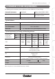
X100 Series Main User Manual CONFIGURE SETUP INSTALL & CONNECT SPECIFICATIONS X100C WIRELESS IP CUBE CAMERA GENERAL SPECIFICATIONS Image Device 1.3 Megapixel image sensor Resolution 1280 x 1024 pixels Minimum Illumination 0 lux (IR on), 0.1 lux (IR off) Lens 4.
X100 Series Main User Manual 159 AUDIO RTSP: G.711 64kbps, G.726 32kbps 3GPP: AMR Audio Streaming One-way or two-way Microphone Built-in Microphone Audio Output Line Level Out NETWORK TCP, UDP, HTTP, SMTP, FTP, NTP, DNS, DDNS, DHCP, ARP, Bonjour, UPnP, RTSP, RTP, RTCP, PPPoE, 3GPP, ICMP, IGMP, SAMBA Security Password Protection, IP address filtering, User Access Log Users 20 simultaneous unicast users Unlimited users using multicast Ethernet 10/100M Auto Negotiation Wireless Yes, IEEE 802.
X100 Series Main User Manual X104P WIRELESS PAN TILT ZOOM IP CAMERA RECORDING SOFTWARE CONFIGURE SETUP INSTALL & CONNECT GENERAL SPECIFICATIONS Image Device 1.3 Megapixel image sensor Resolution 1280 x 1024 pixels Minimum Illumination 0 lux (IR on), 0.1 lux (IR off) Lens 4.
X100 Series Main User Manual 161 AUDIO RTSP: G.711 64kbps, G.726 32kbps 3GPP: AMR Audio Streaming One-way or two-way Microphone Built-in Microphone Audio Output Line Level Out NETWORK TCP, UDP, HTTP, SMTP, FTP, NTP, DNS, DDNS, DHCP, ARP, Bonjour, UPnP, RTSP, RTP, RTCP, PPPoE, 3GPP, ICMP, IGMP, SAMBA Security Password Protection, IP address filtering, User Access Log Users 20 simultaneous unicast users Unlimited users using multicast Ethernet 10/100M Auto Negotiation Wireless Yes, IEEE 802.
X100 Series Main User Manual X100D IP DOME CAMERA RECORDING SOFTWARE CONFIGURE SETUP INSTALL & CONNECT GENERAL SPECIFICATIONS Image Device 1.3 Megapixel image sensor Resolution 1280 x 1024 pixels Minimum Illumination 0.1 Lux Lens 4.
X100 Series Main User Manual 163 AUDIO RTSP: G.711 64kbps, G.
X100 Series Main User Manual X100V VANDAL RESISTANT IP DOME CAMERA RECORDING SOFTWARE CONFIGURE SETUP INSTALL & CONNECT GENERAL SPECIFICATIONS Image Device 1.3 Megapixel image sensor Resolution 1280 x 1024 pixels Minimum Illumination 0 Lux (IR on), 0.1 Lux (IR off) Lens 2.7 to 9.
X100 Series Main User Manual 165 AUDIO RTSP: G.711 64kbps, G.
X100 Series Main User Manual X100B IP BULLET CAMERA RECORDING SOFTWARE CONFIGURE SETUP INSTALL & CONNECT GENERAL SPECIFICATIONS Image Device 1.3 Megapixel image sensor Resolution 1280 x 1024 pixels Minimum Illumination 0 Lux (IR on), 0.1 Lux (IR off) Lens 4.
X100 Series Main User Manual 167 AUDIO RTSP: G.711 64kbps, G.
X100 Series Main User Manual X100T IP BODY CAMERA RECORDING SOFTWARE CONFIGURE SETUP INSTALL & CONNECT GENERAL SPECIFICATIONS Image Device 1.3 Megapixel image sensor Resolution 1280 x 1024 pixels Minimum Illumination 0.1 Lux Lens 4.
X100 Series Main User Manual 169 AUDIO RTSP: G.711 64kbps, G.
X100 Series Main User Manual X104S VANDAL RESISTANT IP SPEED DOME RECORDING SOFTWARE CONFIGURE SETUP INSTALL & CONNECT GENERAL SPECIFICATIONS Image Device 1.3 Megapixel image sensor Resolution 1280 x 1024 pixels Minimum Illumination 0.1 Lux Lens 4.
X100 Series Main User Manual 171 AUDIO RTSP: G.711 64kbps, G.
X100 Series Main User Manual X100VS VIDEO SERVER (CODEC) SETUP INSTALL & CONNECT GENERAL SPECIFICATIONS LEDs Indicator LEDs Weather Resistant No Mounting Type Free Standing / Desk Mount Power Over Ethernet Yes Operating Voltage 12V DC 500mA Operating Temperature 0°C to 40°C SD Card Slot Yes Inputs DC Power Input BNC Video Input Audio Input Alarm Input RS485 Input Outputs RJ45 Socket (10BaseT/100BaseTX) AV Output Alarm Output 12V DC Power Output (400mA max) Dimensions (WHD) 125 x
X100 Series Main User Manual 173 NETWORK TCP, UDP, HTTP, SMTP, FTP, NTP, DNS, DDNS, DHCP, ARP, Bonjour, UPnP, RTSP, RTP, RTCP, PPPoE, 3GPP, ICMP, IGMP, SAMBA Security Password Protection, IP address filtering, User Access Log Users 20 simultaneous unicast users Unlimited users using multicast Ethernet 10/100M Auto Negotiation Wireless No Power Over Ethernet Yes INSTALL & CONNECT Supported Protocols SYSTEM INTEGRATION Open API for software integration, SDK Alarm Triggers Intelligent Motion D
X100 Series Main User Manual RECORDING SOFTWARE CONFIGURE SETUP INSTALL & CONNECT XVISION SUPPORT At Xvision we provide quality products that perform to the highest standards, while being simple to install and use. If you have any difficulties setting up or using your product please visit our support pages at www.xvision.com for assistance and for details of online and telephone support in your region.
X100 Series Main User Manual 175 WARRANTY (including accidental damage) and damage caused by normal wear and tear. In the unlikely event that you encounter a problem with this product, it should be returned to the place of purchase. INSTALL & CONNECT This product is supplied with a 1 Year warranty.
V1-2/2010-10