INSTRUCTION MANUAL AC2008B INSTALLER: PLEASE LEAVE THIS MANUAL FOR THE OWNER’S USE.
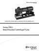
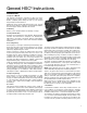
DESCRIPTION PUMP APPLICATION The HSC3 Series centrifugal pumps are frame mounted pumps which feature – high efficiency, rugged construction, compact design, foot mounted volute, center drop out coupler, and regreasable bearings. These features, along with the horizontal split case, make installation, operation, and service easy to perform.
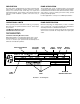
B. SAFETY INSTRUCTIONS SAFETY INSTRUCTIONS This safety alert symbol will be used in this manual and on the pump safety instruction decals to draw attention to safety related instructions. When used the safety alert symbol means ATTENTION! BECOME ALERT! YOUR SAFETY IS INVOLVED! FAILURE TO FOLLOW THE INSTRUCTIONS MAY RESULT IN A SAFETY HAZARD. Additional Safety Requirements: Your HSC3 Pump should have the following safety instruction decals displayed.
ADDITIONAL SAFETY REQUIREMENTS: ELECTRICAL SAFETY: MECHANICAL SAFETY: WARNING: Electrical Shock Hazard Electrical connections to be made by a qualified electrician in accordance with all applicable codes, ordinances, and good practices. Failure to follow these instructions could result in serious personal injury or death, or property damage. WARNING: Electrical Overload Hazard Three phase motors must have properly sized heaters to provide overload and undervoltage protection.
General HSC3 Instructions INTRODUCTION 1. Purpose of Manual This manual is furnished to acquaint you with some of the practical ways to install, operate, and maintain this pump. Read it completely before doing any work on your unit and keep it handy for future reference. Equipment cannot operate well without proper care. To keep this unit at top efficiency, follow the recommended installation and servicing procedures outlined in this manual. 2.
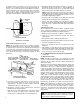
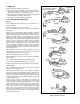
Foundation bolts should be set in concrete as shown in Illustration 3. An optional 4-inch long tube around the bolts at the top of the concrete will allow some flexibility in bolt alignment to match the holes in the base plate. Allow enough bolt length for grout, shims, lower base plate flange, nuts and washers. The foundation should be allowed to cure for several days before the base plate is shimmed and grouted. PIPE SLEEVE d.
12. ANSI/OSHA COUPLER GUARD REMOVAL/INSTALLATION c. With the inner guard straddling the support bracket, install a capscrew through the hole (or slot) in the support bracket and guard located closest to the pump. Do not tighten the capscrew. WARNING: Unexpected Start-up Hazard Disconnect and lock out power before servicing. Failure to follow these instructions could result in serious personal injury or death and property damage. d. Spread the outer guard and place it over the inner guard. e.
Method 1 – Straight Edge Alignment for Standard Sleeve Type Coupler with Black Rubber Insert (See Illustration 5A) Method 2 – For Orange Hytrel Inserts, 3500 RPM Operation, or All Other Coupler Types (See Illustration 5B) Before aligning the coupler, make sure there is at least 1/8" end clearance between the sleeve and the two coupler halves. a. Make sure each hub is secured to its respective shaft and that all connecting and/or spacing elements are removed at this time. 1.
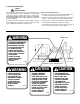
13. DOWELING Dowel the pump and driving unit as follows: a. Drill holes through diagonally opposite feet and into the base. Holes must be of a diameter 1/64 inch less than the diameter of the dowel pins. Clean out the chips. b. Ream the holes in feet and base to the proper diameter for the pins (light push fit). Clean out the chips. CHECK VALVE GATE VALVE SUCTION PIPE INSTALLED WITH A GRADUAL RISE TO PUMP INCREASER LEVEL C L OF PIPE CORRECT AIR POCKET c.
Suction piping should be short in length, as direct as possible, and never smaller in diameter than the pump suction opening. If the suction pipe is short, the pipe diameter can be the same size as the suction opening. If longer suction pipe is required, pipes should be one or two sizes larger than the opening, depending on piping length.
OPERATION 1. Pre-start Checks Before initial start of the pump, make the following inspections: a. Check alignment between pump and motor. b. Check all connections to motor and starting device with wiring diagram. Check voltage, phase, and frequency on motor nameplate with line circuit. c. Check suction and discharge piping and pressure gauges for proper operation. d. Check impeller adjustment, see specific section for proper adjustment. e. Turn rotating element by hand to assure that it rotates freely. f.
CHANGING ROTATION Series HSC3 centrifugal pumps can be operated left hand or right hand when viewed from the pump end of the pump. If you wish to reverse the suction and discharge nozzles, this can be accomplished with the same pump as follows: IMPORTANT: Refer to the disassembly and assembly procedures section of this manual for proper disassembly and assembly techniques: 1. Remove the impeller from the shaft, turn it 180° and replace it on the shaft.
TROUBLE SHOOTING Between regular maintenance inspections, be alert for signs of motor or pump trouble. Common symptoms are listed below. Correct any trouble immediately and AVOID COSTLY REPAIR AND SHUTDOWN. No Liquid Delivered CAUSES CURES 1. Lack of prime. Fill pump and suction pipe completely with liquid. 2. Loss of prime. Check for leaks in suction pipe joints and fittings; vent casing to remove accumulated air. 3. Suction lift too high.
Not Enough Pressure CAUSES CURES 21. Mechanical defects. See items 14 and 15. 22. Obstruction in liquid passages. Dismantle pump and inspect passages of impeller and casing. Remove obstruction. 23. Air or gases in liquid. (Test in laboratory, reducing pressure on liquid to pressure in suction line. Watch for bubble formation.) May be possible to overrate pump to point where it will provide adequate pressure despite condition.
MAINTENANCE 1. General Maintenance Operating conditions vary so widely that to recommend one schedule of preventative maintenance for all centrifugal pumps is not possible. Yet some sort of regular inspection must be planned and followed. We suggest a permanent record be kept of the periodic inspections and maintenance performed on your pump. This recognition of maintenance procedure will keep your pump in good working condition, and prevent costly breakdown.
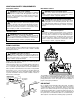
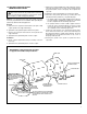
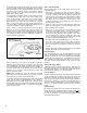
HSC3 Cross-Section Impeller Wear Ring Standard Mechanical Self Flushing Seal CASING PIPE PLUG CASING RING IMPELLER SNAP RING IMPELLER STUFFING BOX “O” RING Impeller Rings can be added — Optional extra.
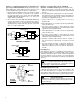
6. Insert threaded rods into the tapped holes in the gland plate and install a fixture on the threaded rods to use a puller. (See Illustration 10 for Dimensions of Universal Fixture PN: AC2394) Using the puller, tighten the bolt in the center of the fixture to remove the bearing and gland plate from the shaft. (See Photos 1 and 2). CAUTION: FAILURE TO REMOVE THE SOCKET-HEAD CAPSCREWS BEFORE TRYING TO PULL THE BEARINGS OFF COULD CAUSE DAMAGE TO THE PUMP. 1.75" 2.0" 2.0" .437 Ø DRILL THRU FOR .
3. Lubricate and roll the O-ring into the groove in the gland plate. IMPORTANT: Steps 4 and 5 must be completed within 10 to 12 minutes to assure proper placement of the mechanical seals. 4. Lightly coat the outboard end of the pump shaft with P-80 Rubber Lubricant Emulsion, vegetable oil, or equal and slide the mechanical seal head onto the shaft. Do not compress the seal spring at this time.
5. Tap the stuffing boxes with a soft-headed hammer to break the seal between the stuffing box and lower casing half, and lift the rotating element out of the lower casing. Rotating element may be removed to a suitable location for repair. NOTE: A spare rotating element can be installed at this point. (See Photo 7) 6. Remove the capscrews from each of the bearing housings and remove the bearing housings by placing two capscrews in the jackscrew holes provided. 7.
Reassembly of the Pump when it is required to remove the Rotating Element of the Pump NOTE: All bearings, O-rings, lip-seals, mechanical seals, gaskets, impeller rings, and casing rings should be replaced with the new parts during assembly. All reusable parts should be cleaned of all foreign matter before reassembling. The main casing joint gasket can be made using the upper and lower half as a template. Lay the gasket material on the casing joint.
14. Lubricate and roll the O-rings into the groove in each stuffing box. NOTE: At this point reassemble the rotating element by starting on the outboard end first (the end opposite the coupling) as this end locates the settings of the mechanical seal. IMPORTANT: Steps 11 through 21 must be completed, on the outboard end, within 10 to 12 minutes to assure proper placement of the mechanical seals. 15.
ORDERING PARTS The pumps covered by this manual have been designed and built with certain replaceable wearing parts. The recommended inventory of spare parts depends upon the installation and the importance of continued operation. Parts should be ordered as far in advance of their use as possible since circumstances beyond the control of the company may reduce existing stock. Not all parts are stocked and must be manufactured for each order.