® INJECTOR MODEL C-1100 MODEL-V VARIABLE SPEED POSITIVE DISPLACEMENT INJECTOR PUMP OPERATING MANUAL Blue-White R Industries, Ltd. 5300 Business Drive Huntington Beach, CA 92649 USA Phone: 714-893-8529 FAX: 714-894-9492 E mail: sales@blue-white.com or techsupport@blue-white.com Website: www.blue-white.
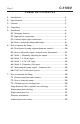
C-1100V Page 2 TABLE OF CONTENTS 1.....Introduction .....................................................................................3 2.....Specifications............. .............. .............. .............. .............. ..............3 3.....Features........ .............. .............. .............. .............. .............. ..............3 4.....Unpacking.... .............. .............. .............. .............. .............. ..............3 5.....Installation ... .............
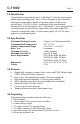
C-1100V Page 3 1.0 Introduction Congratulations on purchasing the C-1100 Model-V Variable speed positive displacement metering pump. The C-1100 is designed to inject chemicals into piping systems and is capable of injecting against a high system pressure up to 150 PSI (10.4 bar).
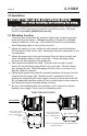
C-1100V Page 4 5.0 Installation CAUTION: Proper eye and skin protection must be worn when installing and servicing the pump. Note: All diagrams are strictly for guideline purposes only. Always consult an expert before installing the pump into specialized systems. The pump should be serviced by qualified persons only. 5.1 Mounting Location Choose an area located near the chemical supply tank, chemical injection point and electrical supply.
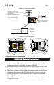
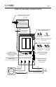
C-1100V Page 5 TYPICAL INSTALLATION Injection / Check valve with 1/4” and 1/2” male pipe threads. Mount in upward position to prevent trapped gasses in the injection fitting.
C-1100V Page 6 5.3 External Input Signal Connections The C-1100V will accept any one of three different types of external input signals; 4-20 mA , 0-10 VDC, or frequency. The 4-20mA and 0-10 VDC loops must be powered. Two types of frequency inputs, AC sine waves (magnetic coils type outputs) and Digital Square waves (Hall Effect signals, contact closures), are acceptable.
C-1100V Page 7 CIRCUIT BOARD CONNECTIONS EXTERNAL INPUT CABLE ACCEPTABLE CABLE JACKET RANGE: .118 - .255 INCH .
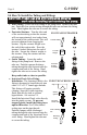
Page 8 C-1100V 5.4 How To Install the Tubing and Fittings CAUTION: Proper eye and skin protection must be worn when installing and servicing the pump. ! Inlet Tubing - Locate the inlet fitting of the pump head. Remove the tube nut. Push the clear suction tubing through the tube nut and onto the fitting barb. Hand tighten the tube nut to secure the tubing.
C-1100V Injection Check valve Page 9 Install upward Tube Nut Discharge Tube (Rigid P.E.
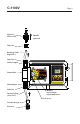
C-1100V Page 10 6.0 How To Operate The C-1100V 6.1 Description of Pump Output Adjustment Controls - Open the control VARIABLE SPEED PUMP MODE 1 RUN PROGRAM 1000 % SPEED mA VDC Hz panel door by sliding the upper and lower slide clamps to the left. ALARM STAND-BY PRIME MINIMUM SERVICE MAXIMUM ! RUN/STANDBY Button 4 Press to start and stop the pump. The ARROW next to the word RUN will light when in the run mode. The ARROW next to the word STAND-BY will blink when in the stand-by mode.
C-1100V Page 11 6.2 How to adjust the output- manual stroke adjustment The ø Pump flow rate can be adjusted within a range of 5% -100% of maximum output (20:1 turndown ration) by means of a mechanical, cam type mechanism. The mechanism adjusts the pump’s stroke length to an infinite number of settings within the flow range. Note: The pump’s output will reduce due to increased system pressure, increased suction lift, and increased fluid viscosity. The pump must be oversized to allow for these factors.
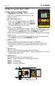
Page 12 C-1100V 6.4 OPERATING MODE 2 - Output adjusted by 4-20 mA input signal - 4 4 4 4 4 4 4 4 4 4 In this mode, the pump’s motor speed is adjusted automatically based on the value of the 4-20 mA input signal. Any motor speed can be assigned to either the minimum or maximum milliamp input values. However, the programmed minimum mA value must be less than the programmed maximum mA value. The ALARM and SERVICE icons will blink if the programming is in error.
C-1100V Page 13 4 maximum value is ready to be programmed. The currently programmed maximum motor speed value is shown on the 3-DIGIT LCD. 4 Enter the motor speed at the maximum mA input signal value. Press the FIELD button to select the digit to program. The digit will blink when selected. 4 Press the DIGIT button to change the selected digit. 4 Repeat until all digits are programmed. 4 Press the mode button.
Page 14 C-1100V 6.5 OPERATING MODE 3 - Output adjusted by 0-10VDC input signal - 4 4 4 4 4 4 4 4 4 4 In this mode, the pump’s motor speed is adjusted automatically based on the value of the 0-10VDC input signal. Any motor speed can be assigned to either the minimum or maximum DC input signal values. However, the programmed minimum VDC value must be less than the programmed maximum VDC value. The ALARM and SERVICE icons will blink if the programming is in error.
C-1100V 4 4 4 4 4 4 4 4 4 indicating the maximum value is ready to be programmed. The currently programmed maximum motor speed value is shown on the 3-DIGIT LCD. Enter the motor speed at the maximum VDC input signal value. Press the FIELD button to select the digit to program. The digit will blink when selected. Press the DIGIT button to change the selected digit. Repeat until all digits are programmed. Press the mode button.
Page 16 C-1100V 6.6 OPERATING MODE 4 - Output adjusted by frequency (Hz) input signal - 4 4 4 4 4 4 4 4 4 4 In this mode, the pump’s motor speed is adjusted automatically based on the frequency (Hz) of the input signal. Any motor speed can be assigned to either the minimum or maximum Hz input signals. However, the programmed minimum Hz value must be less than the programmed maximum Hz value. The ALARM and SERVICE icons will blink if the programming is in error.
C-1100V 4 4 4 4 4 4 4 4 4 Page 17 maximum value is ready to be programmed. The Currently programmed maximum motor speed value is shown on the 3-DIGIT LCD. Enter the motor speed at the maximum VDC input signal value. Press the FIELD button to select the digit to program. The digit will blink when selected. Press the DIGIT button to change the selected digit. Repeat until all digits are programmed. Press the mode button.
Page 18 C-1100V 6.7 Measuring the Pump’s Output - Volumetric Test. This volumetric test will take into account individual installation factors such as line pressure, fluid viscosity, suction lift, etc. This test is the most accurate for measuring the injector’s output in an individual installation. 1. Be sure the Injection Fitting and Footvalve/Strainer is clean and working properly. 2. Fill a large graduated cylinder with the solution to be injected. 3.
C-1100V Page 19 Confirm the FVS flow range - The Flow Verification Sensor (FVS) will only function within its operating range. Sensor model FV100-6V has an operating range of 30-300 ml/min (1-10 oz/min). If the pump’s output is less than 30 ml/min (0.5 ml/sec), the sensor will not detect chemical and a signal will not be sent to the pump.
Page 20 C-1100V 7.0 How to Maintain the Pump CAUTION: Proper eye and skin protection must be worn when installing and servicing the pump. 7.1 Routine Inspection and Maintenance The pump requires very little maintenance. However, the pump and all accessories should be checked regularly. This is especially important when pumping chemicals. Inspect all components for signs of leaking, swelling, cracking, discoloration or corrosion. Replace worn or damaged components immediately.
C-1100V PUMP HEAD AND VALVE EXPLODED VIEW Page 21
7 14 15 12 1 2 4 6 8 9 10 11 13 17 3 5 18 19 16 44 23 45 47 22 25 20 69 24 28 29 49 46 48 33 50 30 51 31 52 32 55 59 42 57 34 54 51 35 53 65 52 36 37 64 56 38 39 66 40 60 68 67 62 41 61 63 Page 22 C-1100V Replacement Parts Drawing
C-1100V Page 23 PARTS LIST Item Part No Description 1 2 3 4 5 6 7 8 9 10 11 12 13 14 15 16 17 18 19 20 22 23 24 25 28 29 30 31 32 33 34 Qty C-345S Screen, FootValve, P.P. 1 90002-214 Body, FootValve, PVDF 1 2-108A O-ring, FootValve, Aflas 1 2-108E O-ring, FootValve, E.P. 1 C-385C Ball, FootValve, Ceramic 1 90003-014 O-ring, FootValve, Viton 1 90003-015 O-ring, FootValve, E.P.
Page 24 C-1100V LIMITED WARRANTY Your new pump is a quality product and is warranted to be free of defects as set down in this policy. All parts, including rubberized goods, and labor are covered under warranty for 90 days from the date of purchase. Used peristaltic pump tube assemblies are not warranted. Parts, excluding rubberized goods, are covered under warranty for 12 months from the date of purchase.
C-1100V Page 25 AUTHORIZED SERVICE CENTERS ARKANSAS BT Environmental, Inc Bill Thomason 225 Castleberry Street Hot Springs, AR 71902 501-624-3837 CALIFORNIA (NORTHERN) Howard E. Hutching co. (Repair Center) 7190 Penryn Plaza Penryn, CA 95663 Pool-Tech, Inc. 3471 Mt. Diablo Blvd. Lafayette, CA 94549 415-284-1400 Swimco Electric Co. 753 Camden Avenue Campbell, CA 95008 408-378-2607 CALIFORNIA (SOUTHERN) Blue-White Industries (Repair Center) 5422 Business Drive Huntington Bch.
C-1100V Page 26 This page blank
C-1100V Page 27 This page blank
Blue-White R Industries, Ltd. 5300 Business Drive Huntington Beach, CA 92649 USA Phone: 714-893-8529 FAX: 714-894-9492 E mail: sales@blue-white.com or techsupport@blue-white.com Website: www.blue-white.com # 80000-387 Rev.