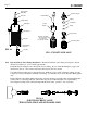
® INJECTOR T B AR E U G H Y A IN A CW C M SE F . N S U L G N W NG E .
C-1500N Page 2 TABLE OF CONTENTS SECTION HEADING PAGE 1 Introduction 2 2 Specifications 2 3 C-1500N Features 3 4 How to install the C-1500N 3 4.1 Mounting location 3 4.2 Electrical connections 5 4.3 How to install the tubing and fittings 6 How to operate the C-1500N 8 5.1 Adjusting the Pump Output - Standard Models 8 5.2 Adjusting the Pump Output - Fixed cycle timer Models 9 5.2 Measuring the pump’s output - volumetric test 9 How to maintain the C-1500N 9 6.
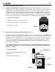
C-1500N Page 3 3.0 C-1500N Features ! ! ! ! ! ! ! ! ! ! ! ! * Double-ball ceramic check valves. PVDF (Kynar) valve assemblies. Viton o-rings. High outlet pressure capability of 125 PSIG.* Easy access, top mounted mechanical feed rate adjustment. Ball bearing supported motor drive shaft. Permanently lubricated ball bearing motor. 20:1 adjustment turn down ratio. Acceptable for outdoor use. (NEMA 3R; IP23) Corrosion resistant Valox housing. Easy servicing.
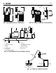
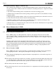
C-1500N Page 4 4-1/2” #10 Self-Tap (2 X) 5-3/4” #10-32 2.30” 9-1/16” Wall Mount Bracket FIG. 4.0 DIMENSIONAL DRAWING 2 3 4 FIG. 4.1 INJECTOR WALL MOUNTING 5 6 7 8 1 Po ol 9 10 1. 2. 3. 4. 5. 6. Strainer Circulation Pump Filter Heater Check Valve Flowmeter ® Blue-White F-300 7. Injector Blue-White® C-1500N 8. Solution Tank 9. Injection Fitting 10. Return Line FIG. 4.2 SWIMMING POOL INSTALLATION C-1500N Discharge Tube Pumping unit Suction Tube (vertical) ¼" & ½" NPT Injector FIG. 4.
C-1500N Page 5 4.2 Electrical Connections 4.2.1 Input Power Connections Be certain to connect the pump to the proper supply voltage. Using the incorrect voltage will damage the pump and may result in injury. The voltage requirement is printed on the pump serial label. Note: When in doubt regarding your electrical installation, contact a licensed electrician. The C-1500N is supplied with either a ground wire conductor and a grounding type attachment plug (power cord) or a junction box for field wiring.
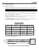
C-1500N Cycle Adjustment Potentiometer Page 6 Timer Board AC AC/LOAD LOAD Hot T1 Common T2 Ground (green) AC Input Power T3 JB1 JB2 JB3 JB1, JB2, JB3 = Voltage Selector Jumpers Neutral Jumpers Configuration Hot Install JB2 & JB3, (JB1 left open) = 24 V AC input Install JB1 & JB3, (JB2 left open) = 115 V AC input Remove all jumpers (JB1, JB2, & JB3 left open) = 220V, 230 V AC input (factory Setting) AC Motor FIG. 4.5 WIRING DIAGRAM - FIXED TIMERS 4.3 How To Install the Tubing and Fittings 4.3.
C-1500N Page 7 Discharge Tube (Rigid P.E.) Footvalve Adapter Tube Nut Suction Tubing O-Ring Outlet Adapter Ceramic Ball Pump Head Ceramic Weight O-Ring Inlet Adapter Footvalve Body FootValve Assembly Tube Nut Must be installed in a vertical position. DO NOT LAY ON SIDE! Footvalve Strainer Suction Tubing (clear PVC) FIG. 4.6 FootValve FIG. 4.7 FOOTVALVE ASSY. 4.3.
C-1500N Page 8 5.0 How To Operate The C-1500N 5.1 Adjusting the Pump Output- Standard models (fig. 5.1) - The C-1500N flow rate can be adjusted within a range of 5% -100% of maximum output (20:1 turndown ration) by means of a mechanical, cam type mechanism. The mechanism adjusts the pump’s stroke length to an infinite number of settings within the flow range.
C-1500N Page 9 5.3 Measuring the Pump’s Output - Volumetric Test. This volumetric test will take into account individual installation factors such as line pressure, fluid viscosity, suction lift, etc. This test is the most accurate for measuring the injector’s output in an individual installation. 1. Be sure the Injection Fitting and Footvalve/Strainer is clean and working properly. 2.
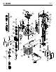
N IO T R R E D N O U T E EN X 18 44 38 9 46 1 45 13 12 42 41 47 37 17 48 35 14 51 48 31 29 49 34 19 13 5 4 3 2 9 A M 32 50 12 53 B AR E U G H Y A IN A CW C M SE F . N S U L G N W G E .
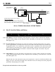
C-535A6-6 C-535A6-6E 71000-324 71000-325 90008-068 70004-074 70004-071 70004-086 90011-141 70000-638 76000-171 90002-077 90002-047 71000-204 71000-205 71000-224 71000-225 71000-226 71000-227 71000-195 90002-146 76000-168 76000-169 70000-683 70000-682 71000-058 71000-057 90006-006 76000-172 90002-001 90001-132 90001-133 90001-134 90001-141 90002-017 90011-168 C-1503N-3 70000-131 70000-133 70000-132 70000-722 1 22 24 25 29 18 19 20 21 17 14 15 16 13 12 10 11 8 9 7 Part No Item Pumphead Kit, HDN V
LIMITED WARRANTY Your new pump is a quality product and is warranted to be free of defects as set down in this policy. All parts, including rubberized goods, and labor are covered under warranty for 90 days from the date of purchase. Used peristaltic pump tube assemblies are not warranted. Parts, excluding rubberized goods, are covered under warranty for 12 months from the date of purchase. Warranty coverage does not include damage to the pump that results from misuse, carelessness, abuse or alteration.