TM CHEM-PRO Diaphragm Metering Pumps C3 Series by Blue-White Industries B DFurDe n I il uilt agm Fan tio phr Dia Detecage 7) p (see Series C3F and C3V Variable Speed Positive Displacement Diaphragm Metering Pump ProSeries TM by Blue-White Industries, Ind. Ltd. www.Blue-White.
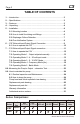
C3 Page 2 TABLE OF CONTENTS 1.....Introduction ......................................................................................3 2.....Specifications ............. .............. .............. .............. .............. ..............3 3.....Features ....... .............. .............. .............. .............. .............. ..............3 4.....Unpacking .... .............. .............. .............. .............. .............. ..............4 5.....Installation .... ..............
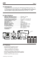
C3 Page 3 1.0 Introduction Congratulations on purchasing the C3 Diaphragm Metering Pump. The C3 is designed to inject chemicals into piping systems and is capable of injecting against a high system pressure up to 175 PSI / 12.1 bar*. 2.0 Specifications Maximum Working Pressure* ..............175 psig / 12.1 bar Maximum Fluid Temperature . ..............130o F / 54o C Ambient Temperature Range . ..............14 to 115o F / -10 to 46.1oC Output adjustment Range ...... ..............
C3 Page 4 4.0 Unpacking Your pump package should contain the following: 1 - Metering Pump 1 - 8 foot / 2.4 meter suction tube, clear PVC 1 - foot valve & strainer assembly 1 - Injection fitting with internal back-flow check valve 1 - Mounting hardware kit (two mounting brackets, 4 screws) 1 - 5 Foot / 1.5 meter Priming Tubing 5.0 Installation CAUTION: Always wear protective clothing, face shield, safety glasses and gloves when working on or near your metering pump.
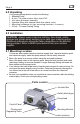
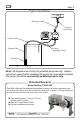
C3 Page 5 Typical Installation Discharge Tubing Injection / Check Valve CHEM-PRO tm C3V | Diaphragm Metering Pump MODE Program Minimum Maximum PRIME Blue-White Ind. Made in the USA TM CHEM-PRO IP66 NEMA 4X Suction Tubing Chemical Tank Priming / Degassing Tubing Foot Valve Note: All diagrams are strictly for guideline purposes only. Always consult an expert before installing the pump into specialized systems. The pump should be serviced by qualified persons only.
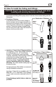
C3 Page 6 5.2 How To Install the Tubing and Fittings CAUTION: Proper eye and skin protection must be worn when installing and servicing the pump and fittings. ! Suction (Inlet) Tubing Locate the inlet fitting of the pump head. Push the clear suction tubing onto the fitting barb. Footvalve / Strainer ! Footvalve / Strainer Trim the inlet end of the suction tubing so that the strainer will rest approximately two inches from the bottom of the solution tank.
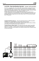
C3 Page 7 5.3 DFD (Diaphragm Failure Detection) The C3 includes DFD sensors built directly into the pump. Although it doesn’t happen often, diaphragm failure can occur. The DFD sensors will detect the chemical behind the diaphragm caused by diaphragm failure. The pump will then shut down and energize an internal 3 amp relay. You can wire the 3 amp relay to an alarm, SCADA system, backup pump, or nothing at all.
C3 Page 8 5.4 FVS - Flow Verification System - (sensor sold separately) The C3 is equipped with a Flow Verification System which is designed to stop the pump and provide a contact closure output in the event the sensor does not detect flow during pump operation. This could indicate a clogged injection fitting, empty chemical solution tank, loose tubing connection, etc.
C3 Page 9 6.0 C3F External Input / Output Signal Connection SIGNAL INPUT/OUTPUT WIRE COLOR CODES INPUT TYPE WIRE COLOR CODE ALARM RELAY connect 2-conductor plug to either normally open (NO) (factory default) or normally closed (NC) side of receptacle.
C3 Page 10 6.1 How To Operate The C3F C3F Series Operation The C3F is a powerful yet simple to operate metering pump.
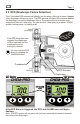
C3 Page 11 7.0 C3V External Input/Output Signal Connection C3V will accept a variety of external control input signals: 4-20mA, 0-10VDC, TTL, CMOS, AC Sine waves, contact closures, Hall Effect, NPN. The 4-20mA and 0-10 VDC loops must be powered. Two types of frequency inputs, AC sine waves (magnetic coils type outputs) and Digital Square waves (Hall Effect signals, contact closures), are acceptable. All wiring connections are to be made inside of the junction box located on the side of the C3V.
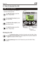
C3 Page 12 7.1 How To Operate The C3V C3V MODE PRIME Series Operation MODE Selection Button Series MODE button is used to select the mode you would like to run the pump in. See below for more MODE information. PRIME button is used to prime the pump. The pump will run at full speed for 60 seconds. To stop the priming function before the 60 seconds, press the Start/Stop button. UP button is used to change the selected digit. Start/Stop button is used to Start and Stop the pump.
C3 Page 13 7.2 OPERATING MODE 1 - Output adjusted manually In this mode, the pump’s motor speed is adjusted manually using the front panel touch pad. The motor speed can be adjusted from 0-100%. 4 Set the pump for mode 1. MODE Press the MODE button until MODE 1 is shown on the LCD display. Mode 1 CHEM-PRO tm C3V | Diaphragm Metering Pump The %SPEED icon will light. The large LCD will indicate the currently programmed percentage of speed.
C3 Page 14 4 Set the pump for mode 2. Press the MODE button until MODE 2 MODE is shown on the LCD display. The %SPEED or mA icon will light depending on the current display setting. Mode 2 CHEM-PRO tm C3V | Diaphragm Metering Pump Program MODE Minimum Maximum The large LCD will indicate the current motor speed or the current mA input value. 4 Enter the programming mode. While MODE 2 is displayed, press the MODE MODE button for more than two seconds. PRIME IP66 NEMA 4X Blue-White Ind.
C3 Page 15 4 Enter the motor speed at the maximum mA input signal value. CHEM-PRO tm C3V | Diaphragm Metering Pump Press the DOWN button to select the digit to program. MODE The digit will blink when selected. Press the UP button to change the selected digit.PRIME Program Minimum Maximum Repeat until all digits are programmed. MODE Press the MODE button. The % SPEED icon will stop Blue-White Ind.
C3 Page 16 7.4 OPERATING MODE 3 - 0-10 VDC Mode In this mode, the pump’s motor speed is adjusted automatically based on the value of the 0-10VDC input signal. Any motor speed can be assigned to either the minimum or maximum DC input signal values. Mode 3 4 Set the pump for mode 3. Press the MODE button until MODE 3 MODE is shown on the LCD display. The % SPEED or VDC icon will light depending on the current display setting.
C3 Page 17 Repeat until all digits are programmed. MODE Press the MODE button. The VDC icon will stop blinking and the % SPEED icon will blink. The ARROW next to the word MAXIMUM will blink indicating the maximum value is ready to be programmed. The currently programmed maximum motor speed value is shown on the LCD. Program Minimum Maximum 4 Enter the motor speed at the maximum VDC input signal value. Press the DOWN button to select the digit to program. The digit will blink when selected.
C3 Page 18 Mode 3 Programming Examples, continued 100% 90% Output Example 2 Pump Output Motor Speed 75% 0 VDC will result in a pump output of 90% 50% 0% Output 25% 0% 0 2 4 6 8 10 VDC will result in a pump output of 0.0% 10 Pump Output Motor Speed VDC input from external source 100% 100% Output 75% Example 3 0 VDC will result in a pump output of 0.0% 50% 0% 25% Output 10 VDC will result in a pump output of 100.0% 0% 0 2 4 6 8 10 VDC input from external source 7.
C3 Page 19 4 Enter the motor speed at the minimum Hz input signal value. Press the DOWN button to select the digit to program. The digit will blink when selected. Press the UP button to change the selected digit. Repeat until all digits are programmed. MODE Press the MODE button. The % SPEED icon will stop blinking and the Hz icon will blink indicating the minimum Hz value is ready to be programmed. The currently programmed minimum value is shown on the LCD.
C3 Page 20 MODE MODE Repeat until all digits are programmed. Press the MODE button. Programming is complete. To exit the programming mode, press and hold the MODE button for more than two seconds. The PROGRAM arrow will disappear. Pump Output Motor Speed Mode 4 Programming Examples 100% 100% Output 75% Example 1 0 Hz will result in a pump output of 0.0% 50% 1000 Hz will result in a pump output of 0.
C3 Page 21 7.6 OPERATING MODE 5 - Batch Mode In this mode, the pump’s ‘motor speed’ and ‘on time’ is configured to be initiated by a single pulse or up to 1,999 pulses. You will configure the pump in the following order: a. Select the % SPEED. (1% to 100%) b. Select the pump ON time. (0.1 to 199.9 and select units: seconds (SEC) or minutes (MIN) c. Select the amount of pulses to receive to trigger the pump. (1 pulse up to 1999 pulses) Mode 5 4 Set the pump for mode 5.
C3 Page 22 Once all the digits are programmed, press the DOWN arrow to then select between SEC (seconds) and MIN (minutes). Use the UP arrow to scroll through SEC and MIN. MODE Press the MODE button. The SEC or MIN icon will stop blinking and the Hz icon will blink indicating the number of pulses is ready to be programmed. 4 Enter the number of pulses to trigger the batch. (1 to 1999 pulses) Press the DOWN button to select the digit to program. The digit will blink when selected.
C3 Page 23 8.0 Measuring the Pump’s Output - Volumetric Test. This volumetric test will take into account individual installation factors such as line pressure, fluid viscosity, suction lift, etc. This test is the most accurate for measuring the injector’s output in an individual installation. 1. Be sure the Injection Fitting and Footvalve / Strainer are clean and working properly. 2. Fill a large graduated cylinder with the solution to be injected. 3.
C3 Page 24 9.0 How to Maintain the Pump CAUTION: Proper eye and skin protection must be worn when installing and servicing the pump. 9.1 Routine Inspection and Maintenance The pump requires very little maintenance. However, the pump and all accessories should be checked regularly. This is especially important when pumping chemicals. Inspect all components for signs of leaking, swelling, cracking, discoloration or corrosion. Replace worn or damaged components immediately.
C3 Page 25 PUMP HEAD AND VALVE EXPLODED VIEW
8 7 5 4 1 10 11 2 9 26 23 21 25 3 21 14 24 6 27 12 15 19 20 18 28 17 29 16 13 30 22 C3 Page 26 Replacement Parts Drawing
C3 Page 27 PARTS LIST Item 1. 2. 3. 4. 5. 6. 7 8. 9. 10. 11. 12. 13. 14. 15. 16. 17. 18. 19. 20. 21. 22. 23. 24. 25. 26. 27. 28. 29. 30. Part No.
C3 Page 28 Intentionally left blank
C3 Page 29 Intentionally left blank
C3 Page 30 LIMITED WARRANTY Your new pump is a quality product and is warranted to be free of defects as set down in this policy. All parts, including rubberized goods, and labor are covered under warranty for 90 days from the date of purchase. Parts, excluding rubberized goods, are covered under warranty for 24 months from the date of purchase. Warranty coverage does not include damage to the pump that results from misuse, carelessness, abuse or alteration.
C3 Page 31 PROSERIES AUTHORIZED SERVICE CENTERS CALIFORNIA (NORTHERN) Howard E. Hutching co. (Repair Center) 7190 Penryn Plaza Penryn, CA 95663 800-568-3958 CALIFORNIA (SOUTHERN) Blue-White Industries (Repair Center) 5300 Business Drive Huntington Bch. CA 92649 714-893-8529 ILLINOIS Mullarkey Associates (Repair Center) 12346 S. Keeler Ave. Alsip, IL 60658 708-597-5558 NEW YORK Sherwood Specialties, Inc.
ProSeries TM by Blue-White Industries, Ind. Ltd. 5300 Business Drive Huntington Beach, CA 92649 USA Phone: 714-893-8529 FAX: 714-894-9492 E mail: sales@blue-white.com or techsupport@blue-white.com Website: www.blue-white.com # 80000-412 Rev.