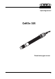
Operating manual CellOx 325 Dissolved oxygen sensor 17
CellOx 325 Copyright © Weilheim 2002, WTW GmbH & Co. KG Reprinting - even as excerpts - is only allowed with the explicit written authorization of WTW GmbH & Co. KG, Weilheim. Printed in Germany.
CellOx 325 Contents CellOx 325 - Contents 1 Overview . . . . . . . . . . . . . . . . . . . . . . . . . . . . . . . . . . . . . . 20 2 Safety . . . . . . . . . . . . . . . . . . . . . . . . . . . . . . . . . . . . . . . . 21 3 Commissioning . . . . . . . . . . . . . . . . . . . . . . . . . . . . . . . . . 21 4 Measuring / Operation . . . . . . . . . . . . . . . . . . . . . . . . . . . 22 4.1 Calibration . . . . . . . . . . . . . . . . . . . . . . . . . . . . . . . . . . . . 22 4.2 Measuring . . . .
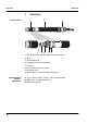
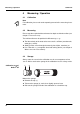
Overview CellOx 325 1 Construction Overview 1 2 4 5 6 3 7 8 1 WP 90 membrane cap (filled with electrolyte solution) 2 Shaft 3 Connection head 4 Gold working electrode (cathode) 5 Insulator 6 Lead counter electrode (anode) 7 Ventilation area 8 Temperature sensor and auxiliary electrode Recommended fields of application 20 l On site measurements in rivers, lakes and wastewater l Applications in water laboratories l BOD measurements
CellOx 325 Safety 2 Safety This operating manual contains special instructions that must be followed during the operation of the Dissolved Oxygen (D.O.) sensor. Always keep this operating manual in the vicinity of the sensor. Special user qualifications The membrane cap of the D. O. sensor is filled with a small amount of an alkaline electrolyte solution.
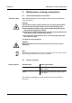
Measuring / Operation CellOx 325 4 Measuring / Operation 4.1 Calibration Note For calibration, please refer to the operating manual of the measuring instrument. 4.2 Measuring Please note the required minimum immersion depth and minimum flow (see chapter 7 TECHNICAL DATA). The minimum flow can be provided in different ways, e. g.
CellOx 325 For your safety Maintenance, cleaning, replacement 5 Maintenance, cleaning, replacement 5.1 General maintenance instructions When dealing with the ELY/G electrolyte solution, observe the following safety instructions: Caution The ELY/G electrolyte solution irritates eyes and skin. When dealing with the ELY/G electrolyte solution, observe the following points: l During working activities, always wear suitable protective gloves and protective goggles/face shield.
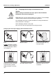
Maintenance, cleaning, replacement 5.3 CellOx 325 Changing the electrolyte and membrane head Caution Before starting to work with the sensor, please note the GENERAL MAINTENANCE INSTRUCTIONS on page 23. General information WTW delivers the sensor ready to operate (see section 3).
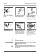
Maintenance, cleaning, replacement G ELY/ CellOx 325 Fill a new membrane cap with ELY/G electrolyte solution. Remove any air bubbles by carefully tapping the membrane head. Additionally, you can prevent air bubbles by throwing the first fill away and refilling the membrane head. ELY/ G Carefully shake off the drops of water. 4 mm Thoroughly rinse the sensor head with electrolyte solution. Hold the sensor inclined and screw on the membrane head fingertight using a paper towel.
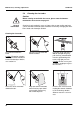
Maintenance, cleaning, replacement 5.4 CellOx 325 Cleaning the electrodes Caution Before starting to work with the sensor, please note the GENERAL MAINTENANCE INSTRUCTIONS on page 23. General information Cleaning is only required in cases of slopes that are too small or too large (sensor cannot be calibrated) that cannot be resolved by changing the membrane head and electrolyte solution. Cleaning the electrodes SF 300 Unscrew the membrane head.
CellOx 325 Maintenance, cleaning, replacement H2O Carefully shake off the drops of water. Remove any air bubbles by carefully tapping the membrane head. Additionally, you can prevent air bubbles by throwing the first fill away and refilling the membrane head. Rinse the sensor head with electrolyte solution. G Water the counter electrode in deionized water for at least 10 minutes. ELY/ ELY/ G Thoroughly rinse the sensor head with deionized water.
Maintenance, cleaning, replacement CellOx 325 Note For measurements under high pressure the fill must be completely free of air bubbles. Readiness to measure After approx. 30 to 50 minutes, the sensor is ready for operation. Subsequently calibrate the sensor. Note If you want to measure very low oxygen concentrations (< 0.5 % saturation), we recommend to let the sensor rest overnight and then calibrate it. 5.5 Checking the sensor for freedom from zero-current The sensor is zero-current free.
CellOx 325 What to do if... 5.6 Disposal Caution The ELY/G electrolyte solution irritates eyes and skin. When dealing with the ELY/G electrolyte solution, observe the following points: l During working activities, always wear suitable protective gloves and protective goggles/face shield. l If it comes into contact with the skin, rinse thoroughly with water and immediately change contaminated clothing. l If it comes into contact with the eyes, rinse thoroughly with water and consult a doctor.
Technical data CellOx 325 7 General features Technical data Measuring principle Membrane covered galvanic sensor Temperature compensation IMT compensation (calculated by the measuring instrument) Dimensions (in mm) Weight Materials Connection cable Pressure resistance 170 g (with 1.5 m cable) Working electrode Gold Counter electrode Lead – – – – POM Shaft Connection head Screwed cable gland Membrane head Membrane FEP, 13 µm Sensor head Epoxy, PEEK Thermistor housing VA steel 1.
CellOx 325 Measurement conditions Characteristic data on delivery Technical data Measuring ranges at 20 °C 0 ... 50 mg/l O2 0 ... 600 % O2 saturation 0 ... 1250 mbar O2 partial pressure Temperature range 0 ... 50 °C Max. allowed overpressure 6·105 Pa (6 bar) Depth of immersion min. 6 cm max. 20 m (depending on the cable length) Operating position any Approach flow > 3 cm/s at 10 % measurement accuracy 10 cm/s at 5 % measurement accuracy 18 cm/s at 1 % measurement accuracy Zero signal < 0.
Wear parts and accessories 8 Wear parts and maintenance accessories Accessories CellOx 325 Wear parts and accessories Description Model Order no.