Global Water 800-876-1172 • globalw.com Global Water Instrumentation, Inc.
Global Water 800-876-1172 • globalw.com Warning Symbol Symbol calls attention to an operating procedure, practice, or the like, which, if This not correctly performed or adhered to, could result in personal injury or damage to or destruction of part or all of the product and system. Do NOT proceed beyond a warning symbol until the indicated conditions are fully understood and met.
Global Water 800-876-1172 • globalw.com Table of Contents I) OVERVIEW ................................................................................................................................... 4 GENERAL ......................................................................................................................................... 4 II) INSTALLATION ...........................................................................................................................
Global Water 800-876-1172 • globalw.com I) Overview General The CR500 is a microprocessor based circle chart recorder. Programmable alarm options combined with “ease of setup” provide the flexibility required for multiple recording applications. This manual will cover both ink type and thermal print versions. The CR500 is the first recorder to “self document” setup configuration during initial setup and can operate using standard or competitive charts.
Global Water 800-876-1172 • globalw.com II) Installation Dangerous voltages capable of causing death are sometimes present when wiring the instrument. Before installation or beginning any troubleshooting procedures, the power to all equipment must be switched off and isolated. Units suspected of being at fault must be disconnected and removed to a properly equipped workshop for testing and repair. Component replacement and internal adjustments must be made by qualified personnel only.
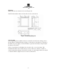
Global Water 800-876-1172 • globalw.com Mounting Make panel cutout to dimension shown in Figure 2.0. Install both mounting clamps and insert the case into panel cutout. Figure 2.0 Mounting Diagram Case Location Upon unpacking, find a suitable location to mount the recorder before wiring power to the unit. Refer to Wiring Precautions (Page 8). After the recorder has been connected to the main AC power supply, connect the battery (optional) to the battery strap and place the battery in its holder.
Global Water 800-876-1172 • globalw.com Wiring Precautions 1) Before wiring, verify the label for correct model number and options. Switch off the power when checking. 2) Care must be taken to ensure that maximum voltage rating specified on the label is not exceeded. 3) It is recommended that power of these units to be protected by fuses or circuit breakers rated at the minimum value possible.
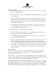
Global Water 800-876-1172 • globalw.com to access the back of the chart plate, please contact GLOBAL WATER INSTRUMENTATION before continuing. Figure 2.1 Power Supply The AC power connections are made to the 4 pin terminal block located on back side of platen. All AC and ground wires must be a minimum of 16 AWG. Refer to Figure 2.1 for proper connection to the main AC power. Earth Ground must be connected at ground lug provided. See Figure 2.
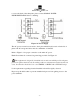
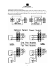
Global Water 800-876-1172 • globalw.com 4-20mA Input Wiring Pen1/Pen2 Transmitters and sensors with 4-20mA outputs can also be connected to the recorder as shown in the following input wiring figures (Figure 2.2). No voltage is provided to power these sensors and must be supplied externally or an optional sensor power supply can be purchased from Global Water. Figure 2.
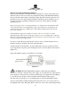
Global Water 800-876-1172 • globalw.com Thermocouple (TC) Installation Guidelines Proper sensor installation can eliminate many problems in a control system. The probe should be placed so that it can detect any temperature change with minimal thermal lag. In a process that requires fairly constant heat output, the probe should be placed close to the heater. In a process where the heat demand is variable, the probe should be close to the work area.
Global Water 800-876-1172 • globalw.com plate. If you are not sure how to access the back of the chart plate, please contact GLOBAL WATER INSTRUMENTATION before continuing. Thermocouple Input Wiring Thermocouple input connections are shown in the following figures. The correct type of thermocouple extension lead-wire or compensating cable must be used for the entire distance between the unit and the thermocouple, ensuring that the correct polarity is observed throughout.
Global Water 800-876-1172 • globalw.com Fig. 2.
Global Water 800-876-1172 • globalw.com RTD Input Wiring RTD connections are shown in the previous, with the compensating lead connected to terminal 4. For two-wire RTD inputs, terminals 2 and 4 should be linked. The three-wire RTD offers the capability of lead resistance compensation provided that the three leads are of same gauge and equal length. Two-wire RTD should be avoided, if possible, for the purpose of accuracy. A 0.
Global Water 800-876-1172 • globalw.com Changing the Chart Press and release the CHANGE CHART key (3 on Figure 2.7). The pen(s) will move to the left of the chart and green LED will flash rapidly. Wait until the pen(s) stops above outer ring AND green LED goes to on steady. Unscrew the chart "hub" knob at the center of the chart. Remove the old chart paper and position the new one so that the correct time line coincides with the time line groove on the chart plate. Refer to Figure 2.
Global Water 800-876-1172 • globalw.com Replacement of Pen “Ink Type” Recorders that are equipped with fiber tipped cartridge pens are colored coded RED for pen 1 and BLUE for pen 2. The pen cartridge is securely fastened to the metal pen arm using a special "U" clip tab. For ease of replacement, it is suggested that the two (2) screws that hold the pen arm be loosened and the pen cartridge and metal pen arm be removed as an assembly. Refer to Figure 2.10 (Page 17) for the location of the pen arm screws.
Global Water 800-876-1172 • globalw.com 3. Follow the thermal pen leads to the main “mother” board located on the back of the recorder platen. 4. Remove the “plug in” thermal print head leads from the main “mother” board. 5. Remove the pen arm screws that attach the pen arm stylus to the pen arm motor assembly located on the front of the platen. 6. Remove the pen arm assembly. 7. Install new pen arm assembly in the reverse order of disassembly. 8. Reconnect AC power to unit.
Global Water 800-876-1172 • globalw.com NOTE: Units with optional display. Display will go BLANK upon AC power loss. Figure 2.
Global Water 800-876-1172 • globalw.com III) Programming Recorder Setup - "Single Pen Ink Type" In order to configure the recorder, you will need the recorder SET-UP CHART. This chart contains the configuration categories of the recorder (Probe Input, Inner Chart Values, Outer Chart Values, Units, Chart Rotation, Input Averaging, and Relay Options). Place the SET-UP CHART onto the recorder. This setup chart should be saved for future reference once setup is complete. 1. 2. 3. 4. 5.
Global Water 800-876-1172 • globalw.com Recorder Setup - Dual Pen (Universal) Input Ink Style In order to configure the recorder, you will need the recorder SET-UP CHART. Universal Inputs allow the user to select a different type of input for each pen. The setup chart contains the configuration categories of the recorder (Probe Input, Inner Chart Values, Outer Chart Values, Units, Chart Rotation, Input Averaging, and Relay Options). Place the SET-UP CHART onto the recorder.
Global Water 800-876-1172 • globalw.com 1. Disconnect power from the unit to be configured. 2. To configure unit for single channel operation, depress and hold the LEFT arrow (1) key. While holding key re-apply power to unit. 3. Hold key depressed for 15 seconds after which, Green LED will turn on. Print arm will begin to move. Unit is now configured for single channel operation. If conversion back to DUAL channel required.
Global Water 800-876-1172 • globalw.com Alarm Settings Ink Style Recorders Alarm setpoint values are selected by positioning the pen to the actual value on the recording chart. Alarm settings can be selected or viewed after CHART CHANGE, recorder setup or during initial power up. To set the alarm setpoint during normal recording operation, complete the following steps. Press and release the CHANGE CHART key (3 on Figure 3.2). Wait until pen(s) moves off scale and LED status changes from flashing to steady.
Global Water 800-876-1172 • globalw.com Alarm Settings Thermal Style Recorders Thermal alarm relay settings can only be set or reviewed from the Setup mode. The SETUP chart must be used for this. Install setup chart. Follow the thermal setup instructions found (See page 10). Alarm settings are set under Alarm #1 and Alarm # 2 setpoint categories. The setup procedure must be followed completely in order to properly store selected alarm values.
Global Water 800-876-1172 • globalw.com Alarm Settings Display Option Features The single red LED display indicates input(s) process variable value with unit(s) during normal operation. In 2 pen units with display, LED display cycles between Pv1 value and Pv2 value. As PV value cycles an additional LED indicates which Pv (1 or 2) value is being displayed. LED display will indicate Hi or Lo if process input variable goes above(Hi) or below(Lo) the programmed range of the recorder scale.
Global Water 800-876-1172 • globalw.com IV) Calibration - Ink Type Only Pen Arm Calibration (Zero and Span) Pen calibration applies to ink type units only and is a two-point calibration. Since Thermal stylus units print their own outer/inner ring, calibration is not necessary. To check and/or adjust the recording pen(s) calibration to the inner and outer graduations of the chart on ink type units, perform the following. 1. Remove power to instrument. If unit has battery option, also remove battery. 2.
Global Water 800-876-1172 • globalw.com Probe Offset Adjust - Ink Style (Pen Offset) This recorder has been accurately calibrated at the factory. Before making any adjustments, this instrument should be in service for 24 hours. Thereafter, if any adjustment is required, perform the following procedure. 1. Place a Certified Test Thermometer(s) alongside the recorder's sensor probe(s) in a monitored controlled condition. 2.
Global Water 800-876-1172 • globalw.com Probe Offset - Thermal Style (Pen Offset) This recorder has been accurately calibrated at the factory. Before making any adjustments, this instrument should be in service for 24 hours. Thereafter, if any adjustment is required, perform the following procedure. 1. Place a Certified Test Thermometer(s) alongside the recorder's sensor probe(s) in a monitored controlled condition. 2.
Global Water 800-876-1172 • globalw.com V) Specifications Power Line Voltage: 110/220VAC, 50/60Hz Power Consumption: 15VA maximum Battery Backup: Standard 9 volt, up to 48 hours of operation Error Protection: De-energized during sensor break NOTE: The CR500 circular chart recorders are not recommended for use in remote non-powered areas.
Global Water 800-876-1172 • globalw.
Global Water 800-876-1172 • globalw.com VI) Default Settings FACTORY SET DEFAULTS Defaults settings are identical for 1 and 2 pen ink or thermal recorders.
Global Water 800-876-1172 • globalw.com VII) Troubleshooting GREEN LED LIGHT SEQUENCE GUIDE 1. LED on steady and pen(s) within chart range, unit is recording normally 2. LED on steady and pen(s) above 100 % ring indicates unit is in CHART CHANGE mode. Action: Press and release CHART CHANGE key to return to normal recording mode. 3. LED flashing RAPIDLY and pen(s) within chart range indicates battery voltage is low. Action: Replace battery. 4.
Global Water 800-876-1172 • globalw.com c. When calling for tech support, please have the following information ready; 1) 2) 3) 4) 5) Model #. Unit serial number. P.O.# the equipment was purchased on. Our sales number or the invoice number. Repair instructions and/or specific problems relating to the product. VIII) Warranty a) Global Water Instrumentation, Inc.
Global Water 800-876-1172 • globalw.
Global Water 800-876-1172 • globalw.com X) GLOSSARY: Input Averaging - The number of input readings (in seconds) held and averaged as pen is recording. The larger the number the more pen response is dampened. High Alarm (Hi) - Output relay energized when process variable above set value. Low Alarm (Low) - Output relay energized when process variable below set value. Band Alarm (Band) - Output relay is energized when process variable is above high set value or below low set value.