F-1000 INSTRUCTION MANUAL Blue-White R Industries, Ltd. 5300 Business Drive Huntington Beach, CA 92649 USA Phone: 714-893-8529 FAX: 714-894-9492 E mail: sales@blue-white.com or techsupport@blue-white.com Website: www.blue-white.
F-1000 Page 2 TABLE OF CONTENTS SECTION HEADING PAGE 1 Introduction 2 2 Specifications 3 3 F-1000 Features 3 4 How to install the F-1000 4 4.1 Mounting location 4 4.2 Pipe Flow Stream Requirements 4 4.3 How to install Your F-1000 Saddle Fitting 6 4.3.1 Drill the Mounting Hole 7 4.3.2 Install the Saddle 7 4.3.3 Check the Saddle Alignment 7 4.3.4 Install the F-1000 Sensor 7 4.4 Installing the F-1000 Machined In-Line Fitting (PI) 8 4.
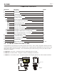
F-1000 Page 3 2.0 SPECIFICATIONS Maximum Working Pressure* 300 psig / 20.7 bar Maximum Fluid Temperature* 200o F / 93.3o C -Saddle and sensor only 200o F / 93.3o C -When mounted on polypropylene and PVDF inline units. 140o F / 60o C -When mounted on molded PVC tee units or PVC pipe. Ambient Temperature Range 32o to 110o F / 0o to 43o C Enclosure NEMA 4X (acceptable for outdoor use) NOTE: Protect the LCD display from direct sunlight.
F-1000 Page 4 4.0 HOW TO INSTALL THE F-1000 4.1 MOUNTING LOCATION Note: All diagrams are strictly for guideline purposes only. Always consult an expert before installing the F-1000 on specialized systems. Note: The F-1000 should be serviced by qualified persons only. Although the F-1000 is designed to withstand outdoor conditions, a cool, dry location where the unit can be easily serviced is recommended. The life of the LCD display will be severely reduced when installed in direct sunlight.
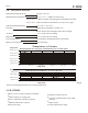
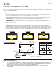
F-1000 Page 5 Pipe Cross Section Flow Velocity Profile Fully Developed Turbulent Flow Disturbed Flow (due to swirling) Laminar Fig.
F-1000 4.3 Page 6 HOW TO INSTALL YOUR F-1000 SADDLE FITTING The F-1000 saddle is designed to mount on smooth schedule 40 IPS pipe, schedule 80 IPS pipe (ASTM-D1785) , PN10 metric pipe or PN16 metric pipe (DIN 8062). The outside of the pipe must be clean, smooth and free of surface imperfections. The outside diameter must be as specified to ensure a leak free installation. The inside diameter must be as specified to ensure meter accuracy.
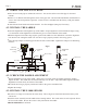
F-1000 Page 7 4.3.1 DRILL THE MOUNTING HOLE ! Select an area on the pipe as outlined in section 4.1. Be sure the surface area of the pipe is clean and smooth. ! Drill a 1-1/8" diameter hole through the center of the pipe wall. On horizontal installations, drill the hole as close to the 12 O'clock position as possible. A hole saw kit is available from the factory, order part number 20000-062. ! Clean all burrs from inside and outside the hole. Use fine sandpaper (440 grit) if necessary. 4.3.
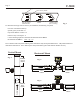
F-1000 4.4 Page 8 INSTALLING THE F-1000 MACHINED IN-LINE FITTING (PI) F-1000 machined in-line fittings consist of a meter body, two pipe adapter fittings (inlet and outlet), and two half union nuts. Pipe adapters are supplied with female American National Standard Taper Pipe Threads (NPT). The adapters are secured to the meter body with half union nuts and sealed with Viton O-rings. ! Select an area on the pipe as outlined in section 4.1. ! Install the F-1000 as you would any other plastic pipe fitting.
F-1000 Page 9 4.5 INSTALLING THE MOLDED IN-LINE FITTING (MI) All molded in-line (MI) fittings have male American National Standard Taper Pipe Threads (MPT). ! Select an area on the pipe as outlined in section 4.1. ! Install the F-1000 as you would any other plastic pipe fitting. Be sure the inlet and outlet fittings are aligned properly. Improper alignment of the fittings will put stress on the adapter connections and may cause leaking or fitting damage. Do not over tighten the fittings.
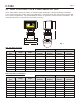
F-1000 5.0 Page 10 HOW TO OPERATE THE F-1000 Note: The calibrated units of measure such as GPM, LPM, M3H, GALLONS, LITERS, CUBIC METERS, ect., And the decimal point location are pre-programmed at the factory to standard flow ranges (see chart). Any unit of measure can be factory programmed. Please contact the factory for details. ! The meter is shipped from the factory with 2 AAA batteries installed. ! When measuring continuous flow (i.e.
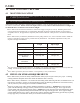
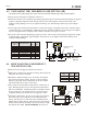
F-1000 Page 11 METRIC PIPES SADDLES - Standard Flow [Min - Max] (Meet DIN 8062) Pipe Size LPM 1 LPH 1 M3H 1 50 MM - PN 10 & PN 16 70.0 - 700.0 4200 - 42000 4.20 - 42.00 63 MM - PN 10 & PN 16 110 - 1100 6600 - 66000 6.60 - 66.00 90 MM - PN 10 & PN 16 230 - 2300 13800 - 138000 13.8 - 138.0 110 MM - PN 10 & PN 16 350 - 3500 21000 - 210000 21.0 - 210.0 160 MM - PN 10 & PN 16 720 - 7200 43000 - 430000 43.0 - 430.0 200 MM - PN 10 & PN 16 1150 - 11500 70000 - 700000 70.0 - 700.
F-1000 Page 12 7.0 HOW TO MAINTAIN THE F-1000 The F-1000 requires very little maintenance, however, some conditions will cause increased wear on the paddle and/or possible damage to the unit. Damage caused by corrosive or abrasive fluids is not covered under warranty. ! Periodically remove the sensor assembly from the pipe fitting and inspect the meter for signs of wear and obstructions. Clean the paddle of any foreign objects. Paddle and axle wear can be caused by chemical attack and/or abrasive fluids.
F-1000 Page 13 9.0 F-1000 PARTS LIST Description Item Part # 1 70000-783 Paddle assembly PVDF 1 2 90003-021 O-ring 022 Viton E60 2 3 90007-589 Axle PVDF 1 4 71000-238 Sensor body assembly F-1000 no paddle 1 5 91001-051 Union nut 1 6 90011-080 Screw #6 x .
F-1000 Page 14 MACHINED IN-LINE BLOCK PARTS LIST ® BLUE-WHITE INDUSTRIES GALLONS PER MINUTE Rate - Totalizer F-1000-RT 1 2 3 4 Pipe Replacement Part Numbers Item 1 Part No . Body .50” 2-20 GPM PP 76100-108 76100-105 76100-107 76100-104 Body .75” 4-40 GPM PP Body .75” .8-8 GPM PP Body 1.0” 6-60 GPM PP 3 4 Body .50” .5-5 GPM PP Machined In-Line Pipe Fittings - U.S. (IPS) F/NPT Kit No Description 38P1 38P2 3/8” In-Line block, .8-8 GPM, PP 3/8” In-Line block, .
F-1000 Page 15 SADDLE PARTS LIST MOLDED IN-LINE BODY PARTS LIST ® BLUE-WHITE INDUSTRIES 1 GALLONS PER MINUTE Rate - Totalizer F-1000-RT 2 Pipe Fitting 3 4 Complete Kit Ordering Numbers Replacement Part Numbers Machined Molded In-Line In-LinePipe PipeFittings Fittings- U.S. - U.S.(IPS) (IPS)M/NPT F/NPT Kit No Description Item Part No . Description 1 76000-830 Alignment tool 2 38M1 38M2 3/8” MPT .800 - 8.000 GPM - PP 91001-115 Saddle, 1-1/2” pipe (50mm) 3/8” MPT .400 - 4.
Warranty ! Blue-White flowmeters are warranted to be free from defects in material and workmanship for 12 months from date of factory shipment. Warranty coverage is limited to repair or replacement of the defective flowmeter only.