
Manual
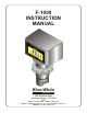


F-1000-RTRate - Totalizer
®
BLUE-WHITE INDUSTRIES
GALLONS PER MINUTE
1.0 INTRODUCTION TO THE F-1000
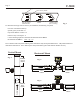
Congratulations on purchasing the F-1000 electronic flow meter. The F-1000 is designed to measure the flow
of a fluid in a pipe. The meter is factory calibrated to any engineering units and displays the rate of flow or the
total of flow on a 6 digit LCD display. Two AAA batteries power the unit for up to one year. There are three
models are available:
F-1000-RB is a rate meter - designed to measure and display the rate of flow.
F-1000-TB is a totalizer meter - designed to measure and display the total flow.
F-1000-RT is a rate/totalizer meter - designed to measure and display both the rate of flow and the total flow.
3. FEATURES
Easy to read .35" high, six digit LCD display.
Weather resistant enclosure.
Installs quickly on existing pipe.
Corrosion resistant PVDF sensor, ABS
Factory calibrated -nothing to program. enclosure.
Minimal maintenance required. High accuracy.
No pressure drop. Large calibrated flow range.
!
!
!
!
!
!!
!!
F-1000
Page 2
F-1000
Page 3
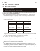
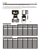
2.0 SPECIFICATIONS
Maximum Working Pressure* 300 psig / 20.7 bar
oo
Maximum Fluid Temperature* 200 F / 93.3 C -Saddle and sensor only
oo
200 F / 93.3 C -When mounted on polypropylene and PVDF inline units.
oo
140 F / 60 C -When mounted on molded PVC tee units or PVC pipe.
oooo
Ambient Temperature Range 32 to 110 F / 0 to 43 C
Enclosure NEMA 4X (acceptable for outdoor use)
NOTE: Protect the LCD display from direct sunlight.
Accuracy +/-2% of full scale rate reading
Repeatability +/-1% of full scale rate reading
Power Requirements Two standard AAA alkaline batteries (included)
Battery Life Expectancy 1 year minimum
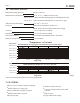
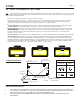
*Temperature vs. Pressure
PSIg (BAR)
PSIg (BAR)
Temperature
Temperature
When mounted on Molded PVC Tee or PVC pipe units
150°F (65.5°C)
175°F (79.4°C)
200°F (93.3°C)
125°F (51.6°C)
100°F (37.8°C)
70°F (21.1°C)
0 (0) 60 (4.1) 120 (8.3) 180 (12.4) 240 (16.5) 300 (20.7)
When mounted on Polypropylene and PVDF inline units or PVDF Saddles
140°F (60°C)
120°F (48.9°C)
100°F (37.8°C)
70°F (21.1°C)
Fig. 2
TABLE OF CONTENTS
SECTION HEADING PAGE
1 Introduction 2
2 Specifications 3
3 F-1000 Features 3
4 How to install the F-1000 4
4.1 Mounting location 4
4.2 Pipe Flow Stream Requirements 4
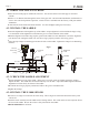
4.3 How to install Your F-1000 Saddle Fitting 6
4.3.1 Drill the Mounting Hole 7
4.3.2 Install the Saddle 7
4.3.3 Check the Saddle Alignment 7
4.3.4 Install the F-1000 Sensor 7
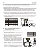
4.4 Installing the F-1000 Machined In-Line Fitting (PI) 8
4.5 Installing the Molded In-Line Fitting (MI) 9
4.6 How to Install Molded PVC Tee Fitting 9
5 How to Operate the F-1000 10
6 F-1000 Flow Ranges 11
7 How to Maintain the F-1000 12
8 Troubleshooting 12
9 Replacement Parts List 13 - 15
*Pressure and temperature limits are inversely proportional.
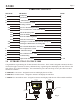
3.03 in.
(77 mm)
2.00 in.
(50.8 mm)
Fig. 1
3.10 in.
(78.7 mm)
Union Nut
4.93 in.
(125.2 mm)
0 (0) 60 (4.1) 120 (8.3) 180 (12.4) 240 (16.5) 300 (20.7)