Hybrid Ultrasonic Flowmeter Installation and Operating Manual
Page 2 Table of Contents Safety precautions. . . . . . . . . . . . . . . . . . . . . . . . . . . . . . . . . . . . . . . . . . . . . . . . . . . . . 4 1 Product overview . . . . . . . . . . . . . . . . . . . . . . . . . . . . . . . . . . . . . . . . . . . . . . 5 1.1 Operating principles . . . . . . . . . . . . . . . . . . . . . . . . . . . . . . . . . . . . . . . 5 1.2 Transit Time operation . . . . . . . . . . . . . . . . . . . . . . . . . . . . . . . . . . . . . 5 1.3 Doppler operation . . . . . . . . .
Page 3 7 8 9 10 6.8 Transit Time transducer installation - Z mount mode . . . . . . 6.9 Transducer acoustic mounting gaskets . . . . . . . . . . . . . . . . . 6.10 Transducer pipe mounting clamps . . . . . . . . . . . . . . . . . . . . . Run mode ....... ....... ....... ....... ....... ....... 7.1 Primary and secondary display areas . . . . . . . . . . . . . . . . . . 7.1.1 Flow rate measurement . . . . . . . . . . . . . . . . . . . . . . 7.1.2 Total flow measurement . . . . . . . . . . . . . . . . . .
Page 4 Safety Precautions Thank you for purchasing the ultrasonic flowmeter. This instruction manual provides important information regarding the safe installation, operation and maintenance of the flowmeter. Please read it carefully before attempting to install or operate the meter. A copy of this manual should be kept by the operator. Extra copies of this manual are available from your supplier or directly from the manufacturer.
Page 5 1.0 Product Overview 1.1 Operating Principles 1.2 Transit Time Operation The Hybrid Ultrasonic Flow Meter can measure fluid flow in virtually any fluid in which sound waves can travel. The meter is considered “hybrid” because it can measure fluid flow using either the Doppler or Transit Time methods. The system includes a set of ultrasonic sound Transducers and a Signal Processing Unit (SPU). The transducers are clamped to the outside of the pipe wall and include no moving parts.
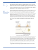
Page 6 1.3 Doppler Operation The Doppler measurement method requires that particles be present in the flow stream to “reflect” the sound waves. The particles must be of sufficient size, volume and type to reflect the sound waves. For example; although orange juice may contain pulp that is of sufficient size and volume, the properties of the pulp do not allow the sound waves to reflect. Therefore, the meter will not operate in the Doppler mode with orange juice containing pulp.
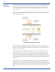
Page 7 1.4 Fluid Requirements Doppler Operation Transit Time Operation ! Must conduct sound ! Must conduct sound ! Must contain sound reflecting particles such ! Must be relatively clean fluid as air bubbles, sand, etc. Doppler measurement requires 0.02% to 15% (200 to 150,000 ppm) particles be present in the flow stream to “reflect” the sound waves. Transit Time measurement requires relatively “clean” fluid. Fluids containing from 0% to 10% (0 to 100,000 ppm) of particles are acceptable.
Page 8 1.7 Standard Model Features and Options STANDARD MODEL FEATURES ! Data logging to a standard SD Card. ! 4-20 mA output signal ! 0-1000 Hz digital frequency output signal ! LED status indicator lights DISPLAY AND USER ACCESS MODEL DISTINCTIONS Model 3 includes a full featured display with a 5 button touch pad. The start-up process and the zero calibration can be performed by pressing the proper buttons on the touch pad.
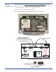
Page 9 WIRING COMPARTMENT The wiring access door on the front of the flowmeter enclosure only must be removed to access the wiring terminal blocks, motherboard controls (a setup button and the measurement mode switch) and to view the status LEDs. The meter is factory set for transit time operation. There are no user serviceable items inside the rear enclosure.
Page 10 2.0 Quick Start Guide 1 MODE SELECT SWITCH Select doppler or transit time mode FUSE 1A 250V (5 x 20) SETUP BUTTON INDICATOR LIGHTS TRANSDUCER INPUTS Tx 1 SIGNAL OUTPUTS T Tx 2 D mA Hz POWER INPUT DC AC WARNING BLK (-) RED (+) RS232 USB GRN RS485 Note that the meter is factory set for Transit-Time operation.
Page 11 3 All pipe types and sizes Determine the transducer mounting mode When operated in the Doppler mode, the transducers are always mounted directly opposite each other, 180 degrees around the pipe. Flow or Flow When operated in the Transit-Time mode, the front faces of the transducers must face each other and be positioned the correct distance apart. In V-mode, the transducers are on the same side of the pipe. In Zmode, the transducers are on the opposite side of the pipe, 180 degrees apart.
Page 12 5 Determine the 2nd transducer location When operated in the Doppler mode, the transducers are always mounted directly opposite each other, 180 degrees around the pipe. All pipe types and sizes “Z” Mount Mode Typically smaller pipe sizes from 2” to 6” Typically larger pipe sizes from 4” to 100” Separation Distance When operated in the Transit-Time mode, the factory configured separation distance and mounting mode is printed on the serial label.
Page 13 6 Configure the meter (continued) Configuration Set #1 Transducer Setup Metering Setup Process Control Setup Reset Working Set to Fact. Defaults Set Password... Save Save As ... Save and Activate ENTER Ç È ESC 5. Highlight Transducer Setup and press enter. ENTER ENTER Ç È ESC ENTER Configuration Set #1 Ç È ESC 13. Highlight Wall Thickness and press enter. ENTER Ç È ESC Ç È ESC ENTER ENTER Ç È ESC Ç È ESC ENTER Ç È ESC 15. Highlight Pipe Material and press enter.
Page 14 Setup Root Menu Manage Configuration Sets Create a New Configuration Set Ê Delete a Saved Configuration Set Ê Activate a Configuration Set Ê Open a Saved Configuration Set Ê Configuration Set #1 Ê Configuration Set #2 Ê Configuration Set #3 Ê Configuration Set #4 Ê Configuration Set #5 Ê Ê Transducer Setup Measurement Units Ê English (U.S.
Page 15 7 DOW 111 Silicone Grease or Install the transducers An acoustic coupling material must be placed between the transducer and the pipe surface at the point where the sound waves enter the pipe. BLUE GASKET - Permenant installations. Recommended for metal pipes. or TRANSDUCER BOTTOM VIEW WHITE GASKET Temporary installations. TRANSDUCER ACOUSTIC COUPLING MATERIAL INSTALLATION Draw a centerline on the pipe parallel to the pipe center. Place the first transducer onto the pipe.
Page 16 3.0 Flowmeter SPU Installation 3.1 Unpacking The Flowmeter is shipped in a carrying case. Inside the carrying case you will find the following items: ! ! ! Flowmeter SPU (Signal Processing Unit) Transducer Set Enclosure Mounting Hardware 2 mounting plates 4 mounting plate screws (10-32 x .50”) 4 panel mount screws (8-32 x 3.00”) 2 wall mounting screws (#10 x 1.
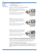
Page 17 3.4 Panel Mounting 1) The SPU can be panel mounted. Measure and cut an opening in the panel as shown. 7.90” (200mm) 10.40” (264mm) 2) Remove the two mounting plates from the rear of the enclosure. 3) Install the gasket onto the rear of the front panel of the SPU enclosure. 4) Place the enclosure into the panel. 5) Re-install the two mounting plates as shown. 6) Thread the four 8-32 x 3.00” machine screws through each of the two outer tapped holes in the mounting plates.
Page 18 3.6 Select the Measurement Method Open the front cover of the SPU. Position the Doppler/Transit-Time switch to the preferred operating mode (factory setting is transit time). Operate the meter in the Transit Time mode (best accuracy) if the fluid contains little or no particles (up to 10% maximum). Operate the meter in the Doppler mode if the fluid to be measured contains more than 10% particles. Doppler/Transti-Time Switch 3.
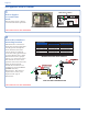
Page 19 Flow Meter Power Input Terminal Block 1 2 Positive (+) 3 Negative (-) 4 5 Line intput Neutral input 110 to 240 VAC 50/60Hz 40 WATTS MAX 15 to 30 VDC 40 WATTS MAX POWER INPUT CONNECTIONS Flow Meter Flow Meter Frequency output (0-1000 Hz) Open Collector output, 50% duty cycle Current output (4-20 mA) Maximum load 1000 ohms Signal Output Terminal Block 1 2 Current input Current output 4-20mA receiver 3 4 Ground 5 (Open Collector output 50% duty cycle) 5k 5-30 VDC Frequency in
Page 20 4.0 Overview of Flowmeter Operation 4.1 Power On and Self-Test On application of power, the power LED (green) on the motherboard comes on and the flowmeter performs self-test functions. The approximate duration of self-test is 10 seconds. The flowmeter indicates that it is in the Self-Test State as follows: Model 1: the red and all four yellew LED indicator lights flash at 1 Hz.
Page 21 When power is applied, the flowmeter enters the Startup state. In the Startup State, the flowmeter waits for up to 7 seconds for the Setup button to be pressed at which time the Setup mode is entered and changes to the configuration can be made. If the setup button is not pressed, the flowmeter will enter the Run Mode and attempt to start flow measurement. If the transducers are not installed on the pipe, a fault will occur.
Page 22 4.4 Setup (Configuration) Mode From the Setup mode, a zero calibration can be performed or, if equipped with either the full function display (Model 3) or the optional Communications software, the Setup Root Menu system can be entered and the meter can be configured. The operations that can be performed in the Setup Root Menu are fully described in section 5.0.
Page 23 4.5 Transducer Positioning State In the Transducer Positioning State, the flowmeter waits for the transducers to be correctly positioned on the pipe. When operated in the Transit Time measurement mode, the separation distance of the transducers is computed by the flowmeter from the information in the Transducer Setup branch of the Configuration Menu. The correct separation distance is dependent on the pipe OD, pipe wall thickness, pipe type and chosen mounting mode.
Page 24 4.6 Zero Calibration State If the Transit Time measurement mode is selected, a zero calibration should be performed if possible. There must be no movement of fluid in the pipe during the calibration. It is not necessary to perform zero calibration if Doppler measurement mode is selected, however it is harmless and will have no effect on the measurement.
Page 25 4.7 Run Mode In the Run Mode, the flowmeter performs flow measurement, updates the 4 to 20 mA and pulse signal outputs, displays and logs data and performs process control actions according to the active configuration. The flowmeter indicates that it is in the Run Mode as follows: Model 1: Yellow LEDs indicate the present “Goodness of Measurement”.
Page 26 4.8 Fault and Warning Error Codes (cont.) The flowmeter indicates that it is in the Faulted State as follows: Model 1: The Fault LED (red) flashes to identify the error (note that this LED is on the motherboard and the wiring access door must be opened to see it) . All yellow LEDs are off. INDICATOR LIGHTS IN SELF-TEST STATE 1 T 2.46 in. Model 2: as for Model 1, plus the error code appears in the upper right hand corner of the Run Mode display screen.
Page 27 5.0 Setup (Configuration) Mode The Setup (configuration) Mode screens are available on the Model 3 only. However, if the communications option is included, any of the models 1, 2 or 3 can access the setup mode by using the PC Software Application. 5.1 Menu Navigation The function of the soft buttons for menu navigation is as follows: Perform an appropriate action on the highlighted item: ! Select the item. ! If an editable value, edit the value. ! If the item has options, show the options.
Page 28 5.2 Global Configuration Setup Root Menu Setup Root Menu Global Configuration Ê Communications Settings Master Password Date and Time Save Changes Manage Configuration Sets Global Configuration ENTER Ç È ESC ENTER Ç È ESC Under the Global Configuration menu item, you can change communications settings, enter and/or change the Master Password, set the date and time, and saving the changes.
Page 29 5.2.2 Master Password On selecting this action, you are prompted to supply a Master Password. The master password is “empty” when shipped from the factory. The first time user may enter any master password. Once entered, this master password can be used to enter ANY configuration, as if no other passwords are present. Ç Ç Once a Master Password has been Setup Root Menu entered, upon selecting this action, you will Global Configuration be prompted to supply the Master Ê Master Password Password.
Page 30 5.3 Manage Configuration Sets Under the Manage Configuration Sets menu item, the user is offered actions to manage these Sets in much the same way as files on a computer. Activate a Configuration Set allows the user to apply a Configuration Set to the flowmeter, which will then enter Run Mode and operate according to the configuration information in that Set plus the setting of the motherboard measurement mode switch.
Page 31 5.4 Configuration Edit Menu The Configuration Edit Menu appears if a new Configuration Set is created or if an existing Configuration Set is successfully opened. The banner on the top line identifies the configuration as New Configuration Set or Configuration Set #1, etc. Note that any changes made are held in a temporary “working” Configuration Set and are not stored to a numbered Set until the user explicitly selects this operation.
Page 32 5.4.1.2 All passwords must contain 5 digits. Each of Entering Passwords the five soft buttons represent 2 digits. The using the Soft Buttons numbers 5, 6, 7, 8 and 9 are interchangeable with 0, 1, 2, 3 and 4 (respectively), so only five choices are needed to enter any digit from 0 thru 9. Entering the number 00000 (55555) effectively cancels the password input or deletes an existing the password.
Page 33 5.4.2 Transducer Setup The Transducer Setup branch of the Configuration Edit Menu allows you to establish the fundamental parameters of the flow meter, including the ultrasonic transducers, the pipe to which they are mounted, the liner inside the pipe, if any, and the fluid flowing in the pipe.
Page 34 5.4.2 Transducer Setup (continued) Pipe --> Pipe material allows you to select from a list the material from which the pipe is made. This tells the flowmeter the speedof-sound in the pipe wall. The user can also select Custom Pipe Material in the list and use the Pipe --> Speed of Sound in Custom Material to enter the speed-of-sound directly. This alternative should be used if the correct pipe material is not in the list offered.
Page 35 5.4.3 Metering Setup (continued) Flow Total --> Volume Units allows you to specify the units of measure in which flow totals are displayed and written to log entries. This is independent of the units of measure for flow rates, so that the flow rate units of measure mey be different than the flow total units. As for Flow Rate, a custom unit of measure can be specified.
Page 36 5.4.3 Metering Setup (continued) Signal Output --> Analog Output allows you to specify the mapping of flow rate to the current value at the 4 to 20 mA analog output signal. The mapping is specified by two points on a straight line. Signal Output --> Pulse Output allows you to specify the mapping of flow rate to the frequency of pulses at the digital output signal. The mapping is specified by two points on a straight line.
Page 37 5.4.4 Process Control Setup The Process Control Setup branch of the Configuration Edit Menu allows you to assign each of the three Relay Channels to monitor either the flow rate, flow total, error codes, or be disabled and also to establish appropriate process control settings. For a detailed description of the flowmeter Process Control functions and the precise effect of each setting briefly presented here, see section 8 below.
Page 38 5.4.4 Process Control Setup (continued) Batch Dispensing Settings --> Default Batch Amount allows you to set a default batch volume for the relay channel. On the Process Control run screen for this channel, the user is able to change the batch volume. Values edited on that screen are not saved in the Configuration Set and the default will be restored if the flowmeter restarts.
Page 39 5.4.5 Reset Working Set to Factory Values Configuration Set #3 If you select Reset Working Set to Factory Values from the Configuration Edit Menu, Reset Working Set to Factory Values then all configuration items that are Are you Sure? editable are set to values established by the Factory Configuration.
Page 40 6.0 Transducer Installation 6.1 Select a pipe location that provides a minimum straight length of pipe of at least 10 times the pipe’s nominal pipe size and mark a point that is at least 5 times the pipe Transducer diameter downstream from the nearest pipe fitting. See section 1.6 for the minimum Piping System straight pipe length requirements.
Page 41 6.4 Transducer Separation Distance When the meter is operated in the Doppler measurement method, the transducers are ALWAYS mounted directly opposite each other. The separation is therefore zero. When the meter is operated in the Transit-Time measurement method, the front faces of the transducers must be positioned the correct distance apart. Separation Distance A B The correct separation distance is dependent on the pipe size, pipe type and chosen mounting mode.
Page 42 6.5 Pipe Surface Preparation The pipe mounting surface must be clean, smooth and free of any surface imperfections. Remove all insulation material, loose paint, coatings, etc. Clean the pipe surface thoroughly. Use sandpaper if necessary to remove surface imperfections. Do not mount the transducers over weld seams. Place a mark on the pipe where the first transducer will be located. Be sure to locate the transducers on the side of horizontal runs of pipe.
Page 43 6.7 Transit Time V mounting method: Transit Time If the fluid contains little or no particles (up to 10% maximum), operate the meter using the Transit Time method to obtain the best accuracy. Transducer When the meter is operated in the Transit Time method, marking the second transducer Installation V Mount Mode location is required. The V Mount mode requires careful separation distance measurements.
Page 44 6.8 Transit Time Z-mount method: Transit Time The Z-mount configuration requires that the second transducer be located directly opposite the V-mount location (point B). The Z-Mount method requires careful separation Transducer distance measurements. Inaccurate placement may result in insufficient signal strength and poor accuracy.
Page 45 4) Fold the paper so that the top edge and the marked circumference point touch. 5) Unfold and place a mark on the folded edge. This mark will be exactly one half of the circumference. This mark is the location for the second transducer. TOP EDGE ONE HALF CIRCUMFERENCE FOLD C ONE HALF CIRCUMFERENCE CIRCUMFERENCE FULL CIRCUMFERENCE 6) Once again, wrap the paper around the pipe starting with the top edge corner positioned at the second transducer location (separation distance point B).
Page 46 6.9 Transducer Acoustic Mounting Gaskets An acoustic coupling material must be placed between the transducer and the pipe surface at the point where the sound waves enter the pipe.. Without this material, the ultrasonic sound waves will not penetrate into the pipe. The meter package includes three different gasket materials for this purpose. The blue gasket should be used for permanent installations. This gasket will be damaged be repeated installations.
Page 47 6.10 Transducer Mounting Clamps The meter is provided with five pipe clamps, four to be used for transducer mounting and a fifth for mounting the SPU. A single clamp can be used on a pipe diameter of up to 10 inches. The clamps can be chained together if required for larger pipe diameters. Additional clamps can be purchased from the factory. Carefully place the first transducer onto the pipe so that the front arrow on the transducer is located exactly over the first separation distance mark (A).
Page 48 7.0 Run Mode This section describes the flowmeter operation in the Run Mode. A mock-up of the Run Mode screen is shown at right. This is how it appears for Model 2 and 3 Displays or if it is viewed from the User PC Software application . For Model 2, the only difference is that the SETUP and RELAY soft buttons are absent (blank) on the flowmeter display (but they are still present at the PC). [¢ ¢ ¢ £ ] 1 T 2.46 in. 1480 U.S. Gallons / min 625.38 U.S. Gallons 4345625.
Page 49 7.1.1 Flow Rate Measurement The rate of fluid flow in the pipe is measured by the flowmeter many times per second. To improve accuracy and the stability of the display, these measurements are averaged over a configurable time and new values are presented to the display at a configurable rate. The averaging algorithm used is the Simple Moving Average (SMA), which is “the unweighted mean of the previous n data points”.
Page 50 7.1.2 Total Flow Measurement As well as averaging measurements to display flow rate, the flowmeter totals all measurements divided by the measurement period to compute a totalized flow. This is written to the display at the same configured intervals as for flow readings. The units of measure for total flow can be configured independently of flow rate. Pressing the CLEAR soft button zeros the total accumulated flow if this option has been enabled by the configuration.
Page 51 7.2.3 Sound Speed Display The field on the top right displays either a speed of sound measurement value (if in Transit Time mode) or a zero (if in Doppler mode). When operated in the transit time mode, the flowmeter periodically calculates the speed that sound is traveling through the fluid and displays the resulting value in meters per second. This value is useful for determining the reliability of the measurement and also for configuring the meter for unknown Custom Fluids.
Page 52 7.3 Process Control Status Areas If the flowmeter is fitted with the Process Control Board, three Process Control Status Areas appear on the display under the secondary display area and above the soft button labels. The Model 2, Model 3 and the User PC Software display is the same. Each area is labeled with the relay number to which it refers and shows the status of that relay channel. If a relay channel is disabled in configuration, the corresponding status area will be blank.
Page 53 7.5.2 Digital Pulse Output The digital pulse output has a frequency range of 0 to 1000 Hz. The correspondence of pulse frequency to flow rate can be configured by specifying two (flow rate, frequency) points. Low and high flow rates, which must not be the same, are specified and the frequencies corresponding to each are given. Other flow rates are mapped to pulse frequencies using a straight line through the points specified.
Page 54 7.6.4 Local Log Data Storage (SD Data Card Storage) 7.6.4.1 Inserting and Removing the Memory Card Log entries will be written to the flowmeter’s Flash memory card if one is installed. The flowmeter supports Secure Digital (SD) and MultiMediaCard (MMC) flash memory cards of most common brands and capacities. If a correctly formatted card is not installed appropriately (see below), log entries will not be written but in all other respects the flowmeter will operate normally.
Page 55 7.6.4.3 Rotation and Purging of Log Files (continued) The five-digit numbers of the next log file and the oldest log file on the card are held in a file in the logs sub-directory with the name logindex.txt. If this file does not exist, the flowmeter will create it and start both numbers at 00001. Thus, the first log file will be log00001.txt and as further files (log00002.txt etc.) are created and filled the flowmeter will remember that log00001.txt is the oldest.
Page 56 8.0 Process Control Process Control functions are configured from the Setup Mode as described in section 5.4.4 above. In addition, you can interact with Process Control functions in Run Mode using Process Control Screens for each of the three relay channels. On these screens, you can inspect alarm status, clear alarms, dispense fluid batches, etc. Use of the Setup Mode has been discussed above. This section covers the use of the Process Control Screens.
Page 57 8.2 Batch Dispensing 8.2.1 Manual Batch Start Type When a process control relay channel is configured to monitor Flow Total, it can be used to dispense fluid in batches. A Process Control Screen for a channel configured in this way is shown at right. The RELAY soft button is used to visit each channel in turn and go back to the Run Mode screen. The START soft button is used to initiate a batch.
Page 58 A batch can be canceled (aborted) as follows: ! ! ! ! ! ! Interrupt the batch as described above. While the batch is stopped (the relay is de-energized), use the or Ç È soft buttons to navigate to and highlight the Total this Batch: status line. The CLEAR soft button replaces the RESUM soft button. Press the CLEAR soft button. The value of Total this Batch: is cleared to zero. All lines are de-selected and the START soft button returns.
Page 59 Ensure that the flow rate, batch amount and relay timer are set up so that the relay will de-energize before the end of each batch. Should the relay still be energized when the end of a batch is detected, then the time at which the relay will de-energize will be extended to the Relay Timer time from the new batch ending. If this repeats, the relay could remain continuously energized. If the STOP soft button is pressed: ! ! ! ! ! The relay channel Status: is indicated as PAUSED.
Page 60 8.3 Flow Rate Alarms When a process control relay channel is configured to monitor Flow Rate, it can be used to indicate that the rate of fluid flow has reached or passed configured trigger values. A Process Control Screen for a channel configured in this way is shown at right. The RELAY soft button is used to visit each relay channel in turn and go back to the Run Mode screen. The CLEAR soft button can be used to clear an alarm condition while the problem causing the alarm is being rectified. 8.
Page 61 been configured, then at any time the flow falls to or below that value the alarm is automatically cleared and the relay channel returns to the CLEAR state. (This is what the operator is going to be striving for in the ALARMING and CLEARING states.
Page 62 8.3.4 More on Alarm Conditions This section contains additional explanation of the conditions under which an alarm condition is cleared. The flowmeter will clear an alarm condition automatically if and only if a Release value has been set for the Trigger value that caused the alarm. For example, if the alarm was caused by the flow rate falling below the Low Trigger, then the alarm will be automatically cleared if a Low Release has been set.
Page 63 9.0 User PC Software This section describes the Sonic-Pro User PC Software application. Any flowmeter model can be equipped with a Communications Package that includes circuitry, connector panel and custom User PC Software. When connected to a computer running the software, any model can perform the Model 3 functions described in this manual including program editing and data logging downloads directly into the PC.
Page 64 9.2.2 Serial & USB Connection If connecting via RS-232, you must select a SERIAL COM PORT number. If connecting via USB, you must select also select a COM PORT number. This is because the USB connection utilizes a USB/SERIAL conversion method. First connect the USB cable to the SPU. Once connected, the new COM PORT number should automatically appear in the pull-down menu and can now be selected. (It will most likely be the largest number port shown.
Page 65 User Notes Ultrasonic Flowmeter
Page 66 10.0 Indexes 10.1 Complete Flowmeter Model Number System 10.
Page 67 10.3 Specifications General Operation_______________________ SPU (Signal Processing Unit)_____________ Measuring Principle Enclosure Hybrid. User-selectable Doppler or Transit Time operating modes. NEMA 4X (IP66), Powder coated aluminum, SS clamps and hardware. Dimensions: 11.00H x 8.60W x 5.00D inches (279H x 218W x 127D mm) Weight 9.5 lb. (4.3 Kg.) Fluid Types Virtually any acoustically conductive fluid. Transit time mode operation from 0% to 10% (0 to 100,000 ppm) particulate.
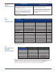
Page 68 10.4 Pipe dimensional data ASTM D 2241 Pressure rated pipe Wall (inches) ASTM D 1785 I.P.S. Pipe Size Schedules Wall (inches) Pipe Size 5s 5 10s 10 20 30 40s & Std. 40 60 80s & XH 80 100 120 140 160 BS 3505 PVC-U Pressure Pipe Wall (inches) XXH SDR SDR SDR Class Class Class Class 41 26 21 B C D E Dn O.D. 2 2½ 3 3½ 4 5 6 8 10 12 14 16 18 20 22 24 26 28 30 32 34 36 42 48 2.375 .065 .065 .109 .109 .154 .154 .218 .218 .344 .436 .091 .113 .118 .145 .177 2.875 .083 .083 .
Page 69 Pipe Dimensional Data DIN 8062 PVC-U Pipe Wall (millimeters) Pipe Size Dn O.D. 63 75 90 110 125 140 160 180 200 225 250 280 315 355 400 450 500 560 630 63 PN 4 PN 6 PN 10 PN 16 PN 20 1.9 3.0 4.7 7.0 75 1.8 2.2 3.6 5.6 8.4 90 1.8 2.7 4.3 6.7 10.0 110 2.2 3.2 5.3 8.2 12.3 125 2.5 3.7 6.0 9.3 140 2.8 4.1 6.7 10.4 160 3.2 4.7 7.7 11.9 180 3.6 5.3 8.6 13.4 200 4.0 5.9 9.6 14.9 225 4.5 6.6 10.8 16.7 250 4.9 7.3 11.9 8.2 13.4 20.8 9.2 15.
Page 70 10.5 Sound speed data Fluid Sound Speeds Fluid Pipe Sound Speeds Temp.
Page 71 10.
Page 72 10.
Page 73 10.
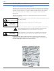
Users of electrical and electronic equipment (EEE) with the WEEE marking per Annex IV of the WEEE Directive must not dispose of end of life EEE as unsorted municipal waste, but use the collection framework available to them for the return, recycle, recovery of WEEE and minimize any potential effects of EEE on the environment and human health due to the presence of hazardous substances. The WEEE marking applies only to countries within the European Union (EU) and Norway.