AQUAVAR AV II ® Variable Speed Pump Control Installation Programming & Operation Models covered: All AV2 Model AQUAVAR II Controllers software revision 120 UL ® IM131R01
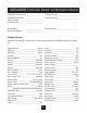
AQUAVAR II Controller Owner’s Information Record AQUAVAR II Controller Model AQUAVAR II Serial Number Date purchased Purchased from _________________ _________________ _________________ _________________ Transducer Model_______________________ Transducer Rating_______________________ Pump Model _________________ Software Version _______________________ Pump Code Number _________________ Program Record Please use the following to record the final values programmed into the AQUAVAR controller after in
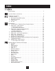
Index Index System Design . . . . . . . . . . . . . . . . . . . . . . . . . . . . . . . . . . . . . . . . . . . . . . . . . . 5 ! ▼ ▼ Important Safety Instructions . . . . . . . . . . . . . . . . . . . . . . . . . . . . . . . . . . . . . 6 Installation Procedures . . . . . . . . . . . . . . . . . . . . . . . . . . . . . . . . . . . . . . . . . . . 9 Materials Checklist . . . . . . . . . . . . . . . . . . . . . . . . . . . . . . . . . . . . . . . . . . . . . . 9 1. Mounting the AQUAVAR II Controller . .
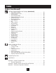
Index Index (continued) Operator Custom Features and Displays (continued) • Actual Value Decrease . . . . . . . . . . . . . . . . . . . . . . . . . . . . . . . . . . . . . . . . 65 • Enable Sequence Control . . . . . . . . . . . . . . . . . . . . . . . . . . . . . . . . . . . . . . 65 • Switch Interval . . . . . . . . . . . . . . . . . . . . . . . . . . . . . . . . . . . . . . . . . . . . . 65 • Source Required Value . . . . . . . . . . . . . . . . . . . . . . . . . . . . . . . . . . . . . . .
System Design System Design - Typical Constant Pressure Systems Note Systems MUST be designed by qualified technicians only. The following diagrams show typical single pump and multi-pump systems using the AQUAVAR controller. Connection can be made directly to a water supply or water can be drawn from a supply tank or well. In the case of supply tanks and wells, level switches, (item 10) can be used to shut down the pumps when water is low.
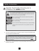
Safety Instructions Important: Read all safety information prior to installation of the AQUAVAR controller. Note This is a SAFETY ALERT SYMBOL. When you see this symbol on the pump or in the manual, look for one of the following signal words and be alert to the potential for personal injury or property damage. DANGER Warns of hazards that WILL cause serious personal injury, death, or major property damage. WARNING Warns of hazards that CAN cause serious personal injury, death, or major property damage.
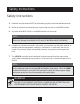
Safety Instructions Safety Instructions 3. Installation and maintenance MUST be performed by properly trained and qualified personnel. 4. Review all instructions and warnings prior to performing any work on the AQUAVAR controller. 5. Any safety decals MUST be left on the AQUAVAR controller unit and pump. Note Inspect AQUAVAR controller for any damage after unpacking from shipping crates. Report any damage immediately to the carrier or distributor/dealer immediately. 6.
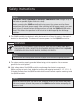
Safety Instructions Note TOUCHING THESE COMPONENTS SERIOUSLY ENDANGERS LIFE! Voltages of up to 800 volts are possible (higher if there is a fault). Before removing the AQUAVAR controller drive top cover, the system must be disconnected from the main power supply. After switching off the power supply, you must wait at least 5 minutes before starting work on or inside the AQUAVAR controller drive head. This allows the capacitors in the circuit to be discharged by the discharge resistors. 8.
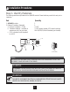
Installation Procedures Step 1- Identify Materials The following materials are provided with the AQUAVAR II controller. Please familiarize yourself with each prior to installation. Part Quantity 1. AQUAVAR Controller 2. Pressure Transducer Assembly a. Pressure transducer - 25 bar b. Transducer adapter - (available as separate part only) See price book. c. 30 ft. transducer cord (standard) for AV II.
Installation Procedures Step 2 - Mounting the AQUAVAR II controller: AQUAVAR Controller The AQUAVAR controller may be installed as a wall or panel mounted unit. The AQUAVAR controller may be mounted up to 60 feet away from the pump motor*. In addition, alternative motor enclosures may be selected such as ODP, explosion proof or wash down motors in addition to the TEFC enclosure required for on the pump mounting. Typical applications for the AQUAVAR Wall Mount controller include: 1.
Installation Procedures Step 2 - Mounting the AQUAVAR controller: (continued) Diagram 3 HP Rating 1 – 10 (230 – 3) 1 – 5 (230 – 1) 1 – 20 (575) 15 – 20 (230 – 3) 71⁄2 – 10 (230 – 1) 25 – 40 (460) 25 – 40 (575) 25 – 75 (460) 25 – 75 (575) A in (mm) B in (mm) C in (mm) D in (mm) E in (mm) F in (mm) G in (mm) 3.20 (81.28) 7.88 (200.15) 16.50 (419.10) 9.32 (236.70) 17.44 (442.98) 12.08 (306.71) 0.28 (7.11) 3.20 (81.28) 7.88 (200.15) 19.25 (488.95) 11.44 (290.53) 20.19 (512.83) 13.51 (343.
Installation Procedures Power Rating HP 25 30 40 50 60 75 Weight Pounds 52.0 52.0 60.0 107.0 107.0 107.0 Kilograms 23.6 23.6 27.2 48.6 48.6 48.6 Electrical Connections WARNING WARNING! FAILURE TO DISCONNECT AND LOCKOUT ELECTRICAL POWER AND WAIT FIVE MINUTES FOR CAPACITOR DISCHARGE BEFORE SERVICING AQUAVAR CONTROLLER CAN CAUSE SHOCK, BURNS, OR DEATH. Hazardous voltage can shock, burn or cause death.
Installation Procedures Electrical Connections continued Step 3 - Preliminary Inspection Before storing or installing the AQUAVAR controller, thoroughly inspect the device for possible shipping damage. Upon receipt: 1. Remove the controller from its package and inspect exterior for shipping damage. If damage is apparent, notify the shipping agent and your sales representative. 2. Remove the cover and inspect the controller for any apparent damage or foreign objects.
Installation Procedures Electrical Connections continued Step 5 - Considerations for Mounting AQUAVAR Controllers in Host Enclosures The AQUAVAR controller is available from stock in a variety of enclosures that meet the requirements of almost any application. Yet, special applications (such as use in washdown environments or in integrated systems) may make it desirable to mount AQUAVAR controllers in a host enclosure.
Installation Procedures Electrical Connections continued Table 2: Required Dissipation for Models Entirely Inside an Enclosure AQUAVAR Model AV2V2S010D 2S020D 2S030D 2S050D 2S075D 2S100D 20010D 20020D 20030D 20050D 20075D 20100D 20150D 20200D 40010D 40020D 40030D 40050D 40075D 40100D 40150D 40200D 40250D 40300D 40400D 40500D 40600D 40750D 50010D 50020D 50030D 50050D 50075D 50100D 50150D 50200D 50250D 50300D 50400D 50500D 50600D 50750D Switching Frequency Max.
Installation Procedures Electrical Connections continued Table 3: Required Dissipation When Fins are External to the Enclosure AQUAVAR Model AV2V2S010D AV2V2S020D AV2V2S030D AV2V20010D AV2V20020D AV2V20030D AV2V20050D AV2V20070D AV2V20100D AV2V20150D AV2V20200D AV2V40010D AV2V40020D AV2V40030D AV2V40050D AV2V40070D AV2V40100D AV2V40150D AV2V40200D AV2V40250D AV2V40300D AV2V40400D AV2V40500D AV2V40600D AV2V40750D AV2V50010D AV2V50020D AV2V50030D AV2V50050D AV2V50070D AV2V50100D AV2V50150D AV2V50200D AV2V5025
Installation Procedures Electrical Connections continued Step 6 - Maintenance Minimum Torque Values to Secure Cover If you remove the cover of an IP55 AQUAVAR controller, it is imperative that the cover be closed and re-secured with sufficient tightness to maintain environmental integrity. The table below specifies the torque values for the bolts that secure the covers on the various models.
Installation Procedures Electrical Connections continued • Use circuit breakers on the incoming power lines. • Grounding must be in accordance with NEC and CEC. If multiple AQUAVAR controllers are installed near each other, each must be connected to ground. Take care to not form a ground loop. Maintain a common ground. • Wire must be made of copper and rated 60 / 75ºC (unless otherwise specified in the table below). Refer to Tables 4, 5 and 6 for recommended wire gauges and temperature ratings.
Installation Procedures Electrical Connections continued Table 5: Recommended Wire Gauges (460 Vac Models) Model Number AV2V40010D AV2V40020D AV2V40030D AV2V40050D AV2V40075D AV2V40100D AV2V40150D AV2V40200D AV2V40250D AV2V40300D AV2V40400D AV2V40500D AV2V40600D AV2V40750D Wire Size AWG 14 14 14 14 12 12 10 101 81 61 61 31 21 11 mm2 2.5 2.5 2.5 2.5 4.0 4.0 6.0 6.01 10.01 16.01 16.01 35.0 35.01 50.01 (1) Use wire rated 90ºC in an environment where the ambient temperature is greater than 40ºC (122ºF).
Installation Procedures Electrical Connections continued Step 8 - Input Line Requirements Line Voltage See the Power and Current Ratings table for the allowable fluctuation of AC line voltage for your particular model. A supply voltage above or below the limits given in the table will cause the drive to trip with either an overvoltage or undervoltage fault.
Installation Procedures Electrical Connections continued Phase Imbalance Phase voltage imbalance of the input AC source can cause unbalanced currents and excessive heat in the drive’s input rectifier diodes and DC bus capacitors. Phase imbalance can also damage motors running directly across the line. CAUTION! EQUIPMENT DAMAGE HAZARD - NEVER USE POWER-FACTOR CORRECTION CAPACITORS ON MOTOR TERMINALS T1/U, T2/V OR T3/W. DOING SO WILL DAMAGE THE SEMICONDUCTORS.
Installation Procedures Electrical Connections continued Typical Power Connections Diagram 5 shows the terminal connections for line power and motor output. See Step 8 for input line requirements. Note that when testing for a ground fault, do not short any motor lead (T1/U, T2/V or T3/W) back to an input phase (L1/R, L2/S or L3/T). As shown in Diagram 5, it is necessary to provide fuses and a disconnect switch for the input AC line in accordance with all applicable electrical codes.
Installation Procedures Electrical Connections continued Table 10: Recommended Fuses (460 Vac Models) Model Number AV2V40010D AV2V40020D AV2V40030D AV2V40050D AV2V40075D AV2V40100D AV2V40150D AV2V40200D AV2V40250D AV2V40300D AV2V40400D AV2V40500D AV2V40600D AV2V40750D Fuse Size 380 Vac JJS/JJN1 6 6 10 15 20 20 40 50 60 70 80 90 110 150 Fuse Size 460 Vac JJS/JJN1 6 6 10 15 20 20 35 40 50 60 60 90 110 150 (1) For sizes up to and including 30 A, KTK fuses may be substituted.
Installation Procedures Electrical Connections continued 220 Volt 460 Volt 1 7 4 2 8 5 V 3 9 6 4 U 9 W 8 3 5 7 2 U AQUAVAR 6 1 W AQUAVAR V 1. The wires routed from the terminal block U, V, W, and ground screw, should now be connected to the motor leads using the motor nameplate and Diagram 6 for reference. Always refer to motor wiring nameplate. GROUND = PE GROUND = PE 2.
Installation Procedures Electrical Connections continued 3. Place the square gasket over the end of the transducer, plug the cable connector on, and tighten the screw. • The transducer is supplied with 1⁄4” NPT threads for direct mounting in the discharge piping. Note Cable connector will fit on one way only! Do not force on or damage may occur. 4. Now select one of the remaining ports in the AQUAVAR controller to route the transducer cable.
Installation Procedures Electrical Connections continued Table 12: Description of AV II Drive Control Terminals (Internal Drive) Terminal RC1 NC1 NO1 RC2 NC2 NO2 EN D3 to D10 D2 D1 Description TB2 Terminal Block Common terminal for the first auxiliary relay. The function of the relay is set by parameter R1 Configure. The default setting is for the relay to activate when a fault is detected (Drv Flted). Normally-closed contact for the first auxiliary relay. It will open when the relay is activated.
Installation Procedures X5 14 13 12 11 10 9 8 7 6 5 4 3 2 1 X2 6 5 4 3 2 1 4 3 2 1 6 5 4 3 2 1 X1 X5 14 13 12 11 10 9 8 7 6 5 4 3 2 1 X2 X2 6 5 4 3 2 1 4 3 2 1 X1 X5 4 3 2 1 X1 6. For multi-pump systems: Use a three core shielded cable to connect terminals 1, 2, and 3 on X5 between the AQUAVAR controller units. These are the RS-485 interface connections. (See Diagram 11 and 13). Note: either RS485 port can be used.
Installation Procedures Pump Priming Refer to your pump operation manual for instructions on pump priming. You will need to unscrew the pressure transducer and adapter if you used the pump fill plug for mounting. When priming is complete, replace the pressure transducer and check for leaks! Run Test WARNING DO NOT APPLY POWER TO THE AQUAVAR CONTROLLER OR PUMP UNTIL ELECTRICAL CONNECTIONS HAVE BEEN REVIEWED BY A QUALIFIED ELECTRICIAN AND MEET ALL APPLICABLE STATE AND LOCAL REQUIREMENTS. Instructions 1.
Installation Procedures Screen 4. Check Display. * If these conditions exist, proceed. If NOT, check all wiring. NO AUTOSTART - DISABLED INV. 5. Drive Component Keypad (Internal Drive) The AQUAVAR II units have an additional keypad inside the cabinet. You will need to use this keypad one time for initial system set up. Once set, all other functions are programmed with the main display on the front panel. Below are the instructions for initial programming of the internal keypad.
Installation Procedures (continued) G. Use the up or down arrow keys to change the parameter’s value to the desired value. H. Press ENTER to save the new value. (If you do not wish to save the new value, press SHIFT.) I. The new value is stored, or discarded, and then the list of parameters is shown. J. You may now select another parameter or return to the Operate mode by pressing the PROG key. 6. You need to set up the AQUAVAR controller for the type of pump motor you are using.
▼ ▼ Programming Installation Procedures continued 19. If the direction of rotation was correct, proceed to the Programming section beginning on the following page. 20. If the direction was not correct, remove all power from the AQUAVAR II controller and wait five minutes. Open the motor conduit box and exchange any two of the three motor leads. Close the conduit box. Repeat steps 15 through 18 to check the direction of the motor shaft rotation.
Programming Screen Instructions 1. Check Power Light NO AUTOSTART - DISABLE INVERTER 2. Press the down arrow▼to advance the display to: 3. Press Select * to advance the display to: INVERTER STOP - ON->START REQUIRED VALVE - XXX PSI Note If “Inverter Locked” is displayed, the external on/off switch is in the off position or contacts at X1:4 and 5 are not jumpered. 4. Enter the pressure ▼you want the pump to maintain (constant pressure) for your system.
Programming Note If you have advanced past a window and want to return to it, press the same time to back up. * * ERROR 1 * ERROR 2 * ERROR 3 * ERROR 4 6. Press to advance the display to: This display shows the last recorded error or fault encountered by the AQUAVAR controller. 7. Press to advance the display to: This in the error which occurred before the last one. 8. Press to advance the display to: The error before error 2. 9. Press to advance the display to: The error before error 3. * 11.
Programming AQUAVAR II Controller Program Flow Chart Single Pump Constant Pressure SW Ver. Date: Press • long ITT Ind. 50 PSI REQUIRED VALUE 50 PSI Auto-START ON ERROR 1 ERROR 2 ERROR 3 ERROR 4 ERROR 5 TOTAL RUN TIME 0000: 41 SAVE ?? –+v Diagram 13 WARNING FAILURE TO SAVE SETTINGS AFTER PROGRAMMING RESULTS IN LOSS OF PROGRAM VALUES WHEN POWER IS REMOVED! II.
Programming ▼ 2. Press the key until you reach the number 66. You will now be able to access all of the alternate menus for all AQUAVAR controller optional controls. * 3. Press to advance the display to the next window: The jog mode is very useful because it allows you to check on the actual outgoing frequency and system pressure. By pressing either or ▼ the controller changes to manual, and you can change the frequency to set any constant speed.
Programming Press the ▼ to enter the number of seconds. The pump will run after pressure begins to drop at pump run out or a suction switch activates. ▼ 15 SEC 8. Error Reset Turning this control on will enable the AQUAVAR II controller to retry its operation five times when a fault condition occurs. Turning the control to “off” means that the AQUAVAR II controller will shut down the first time a fault occurs. Select the mode you want by pushing the up or down arrow key.
37 LEVEL 1 2.0% Diagram 14 OFFSET – INPUT OFF ADC REFERENCE Local PUMP ADDRESS OFF LEVEL 2 0.0% INTENSITY 1 0.0% ENABLE SEQ. CTL. 58.0 Hz FREQU. – LIFTING 37.0 Hz SUBMENU RS485– Interface SUBMENU Seq. Control SUBMENU Offset ACTU. VALUE DEC. 2.1 PSI SENSOR– CURVE Linear SENSOR– ADJUST out of range ACTU. VALUE INC. 5.0 PSI RAMP HYSTERISIS 80% WINDOW 5% JOG-MODE XX Hz XX PSI PASSWORD 0000 ERROR 1 Auto-START ON REQUIRED VALUE 126.9 PSI ITT Ind. 50 PSI Press • long SW Ver.
Programming III. Single Pump - System Curve Compensation The AQUAVAR controller can automatically compensate for system friction losses due to increased flow. Tables are available in most pump catalogs indicating the amount of friction loss that can be expected in various sizes of pipe at different flow rates. Use these tables to determine the friction loss for the pipe size you are using at your maximum flow rate. H f = 100% %f WINDOW Diagram 15 shows a typical system curve.
Programming Entering compensation values: For steps 1 through 4, refer to the flow chart. Instructions Screen * 1. From the main menu, hold down the key for 2-3 seconds until the display changes to: ▼ • Enter 66 by pressing the PASSWORD 0000 0066 2. Freq.- Lifting 30.0 hz This indicates the speed (flow rate) at which you want the pressure compensation to begin. On a 60 hz system, there is virtually no flow below 40 hz. Set this frequency with the up arrow.
40 LEVEL 1 2.0% Diagram 16 OFFSET – INPUT OFF ACTU. VALUE INC. 5.0 PSI LEVEL 2 0.0% INTENSITY 1 0.0% ENABLE SEQ. CTL. 58.0 Hz INTENSITY 2 0.0% SWITCH INTERVAL 12 hours SOURCE REQ. VALUE ADR1 SYNCHRON. LIMIT 0.0 Hz SUBMENU Synch. Control ADC REFERENCE Local PUMP ADDRESS OFF ACTU. VALUE DEC. 2.1 PSI DIMENSION UNIT PSI ANALOGUE – OUT Actual Value LIFT INTENSITY 0.0% FREQU. – LIFTING 37.0 Hz SUBMENU RS485– Interface SUBMENU Seq.
Programming Circulator applications On circulator pumps, the system curve can be automatically tracked through the use of a differential pressure transducer. This pressure transducer reads the outgoing discharge pressure and the incoming return pressure and compensates for differences in pressure as demand and speed increase. Programming is the same as just covered for the single transducer version. Data on the differential pressure transducer can be found in Appendix A. IV.
Programming Single Pump Constant Flow continued ▼ 5. Use the to change the units to GPM if you are using a flow sensor or % if you are using the orifice plate. * * 6. Hold down the 7. Hold down the GPM key until the screen: key until the screen: NORMALIZE 20 mA = 40 GPM 8. Enter either 37 psi for orifice plate application or the maximum flow range of your flow sensor in gpm. ▼ 9.
Programming V. Single Pump - Level Control Applications For drainage applications using a surface pump, the transducer is typically needed to measure pressure on the suction line. As the catch basin or tank empties, the pressure will decrease, and the pump needs to slow down and eventually stop. This is the opposite way the AQUAVAR II controller would usually respond. To change to suction side measurement: 1. On the main menu, enter the PSI value of the liquid at the LOWEST level you want to maintain.
Programming VI. Single Pump - Submersible Applications and Minimum Frequency It is possible to use the wall mounted version of the AQUAVAR II controller with a submersible pump. *Never attempt to mount an AQUAVAR II controller on the pump itself in these applications since the AQUAVAR II controller is not designed to be submerged. The standard distance allowed between the pump and the AQUAVAR II controller is up to 60 feet.
Programming * At the status window, hold the key until you reach the password screen. Enter the password. Use the * MINIMUM FREQUENCY 0 Hz key to advance to: Use the and ▼ to change to the desired minimum frequency (Example 35 Hz). ▼ Use the * PASSWORD 0066 MINIMUM FREQUENCY 35 Hz CONFIG. FMIN F -> FMIN key to advance to: Use the and▼arrow keys to change to: This allows the AQUAVAR II to go down to the selected minimum frequency but not below it. CONFIG.
Programming VII. Setting A Second Fixed Required Value The AQUAVAR II controller can also be used in applications where the required value changes. As an example, a single pump system might be used to supply both water supply and irrigation needs on a farm. When the irrigation system is used, the pressure which needs to be maintained is higher than the pressure for normal water supply.
Programming Enter the submenu by holding the Enter the password and press the Press the ▼ Use the * ITT INDUSTRIES 20 PSI key. * * key. PASSWORD 0066 CONFIG. 2ND REQUIRED VALUE OFF key until you see the screen: and ▼ arrows to change the selection to: CONFIG. 2ND REQUIRED VALUE INT Note The other possibilities (Ext. ADC-1, Ext ADC-U 0-10V, Ext ADC-V 2-10V) involve variable second values controlled by a second sensor. These are discussed in the next section.
Programming VIII. Variable Second Required Value In this section, we will cover the set up and programming of the AQUAVAR II for a second sensor input. This sensor can be either a 4-20mA or 0/2-10V device such as a pressure transducer, flow transducer, heat sensor, etc. When connected to the AQUAVAR II, the output of this second sensor becomes the new set point. As input from the second sensor changes, the set point will also change.
Programming Enter the submenu by holding the Enter the password and press the * Press the ITT INDUSTRIES 20 PSI * * key. key. PASSWORD 0066 CONFIG. 2ND REQUIRED VALUE OFF key until you see the screen: ▼ Use the and▼arrows to change the selection to: EXT ADC-1 for 4-20mA input EXT ADC-U 0-10V for 0-10V input EXT ADC-U 2-10V for 2-10V input Advance the display with the * CONFIG.
Offsets It is also possible to use second sensor input as an offset for the primary required value. An example would be locating the second sensor in a supply tank or well and setting an offset so that when the water level got too low, the pump discharge pressure setting would be reduced until the tank or well had recovered.
Programming analogue value 1 Level 1 % Level 2 % required value 75 PSI Intensity 1 - 10% 60 PSI Intensity 2 - 20% 45 PSI additional input 2 0%=4mA (0V/2V) 20% 80% 100%=20mA (10V) At Level 1 and Level 2, you enter the required value in percent from the Second Additional input (20%) and (80%). Intensity one and two depend on the Sensor range of the external value signal. The Intensity 1 that you have entered is valid until you reach Level 1, after reaching Level 1 the Required Value has no offset.
Programming Press INTENSITY 1 +XX.X% key to advance to: * ▼ Use the and ▼arrow keys to enter the % of the INTENSITY 1 required value you want to increase or decrease -10.0% when the second sensor input is below Level 1. The chart on the previous page uses -10% as an example. This represents an application where the second sensor is in a well or tank.
Programming IX. Multiple Pump Constant Pressure and System Curve Compensation When two, three, or four AQUAVAR II controller controlled pumps are connected in a system, they can be programmed to work together to maintain system pressure up to the maximum flow rate of all pumps combined. As the first pump reaches its maximum speed and flow, the second pump will automatically turn on (and so on).
Programming Multiple Pump Constant Pressure... continued Generally, a slight pressure drop is allowed on the first pump before the next is started. This allows for brief system fluctuations without pump cycling. Once the next pump starts, however, you will want the system to resume its normal set pressure. 7 H ∆P 6 ∆P 5 4 P1 P1 + P2 P1 + P2 + P3 3 2 5. To do this, enter the amount of pressure drop you will allow before the next pump starts.
Programming Multiple Pump Constant Pressure... continued Screen 8. Enter the value required. • Press * ACTUAL VALUE INC. 0003 PSI to advance to the next screen: • Enter the PSI drop before the next pump starts. Use this value for each pump in the AQUAVAR controller system. 9. Enable Seq. Ctl. 60.0 hz This tells the next pump when the preceding pump has reached its maximum speed. • Press * ACTUAL VALUE DEC. 000 PSI ACTUAL VALUE DEC. 0002 PSI Screen ENABLE SEQ. CTL. 60.0 HZ.
Programming Multiple Pump Constant Pressure... continued Source Required Value The next screen refers to the use of a second input signal for changing the required value. This was discussed in Section VIII. If a second sensor or switch is used, you must tell SOURCE REQUIRED VALUE the AQUAVAR II which pump has the connection. Use ADR1 the and▼keys to select. ADR1, ADR2, ADR3 or ADR4. If you are not using a second sensor, leave this set to “off” or “disabled”.
Programming Multiple Pump Constant Pressure... continued 12. Pump Address In this section you will give the pump an address number. Generally, the first pump programmed will be number 1, the second will be number 2, and so on. The purpose of this is to help the AQUAVAR II controller sequence the start and stop activity of the pumps in the system including the selection of lead and lag pumps.
58 Diagram 18 OFFSET – INPUT OFF LEVEL 1 2.0% LEVEL 2 0.0% INTENSITY 1 0.0% ENABLE SEQ. CTL. 58.0 Hz INTENSITY 2 0.0% SWITCH INTERVAL 12 hours SOURCE REQ. VALUE ADR1 ADC REFERENCE Local PUMP ADDRESS OFF ACTU. VALUE DEC. 2.1 PSI DIMENSION UNIT PSI ANALOGUE – OUT Actual Value LIFT INTENSITY 0.0% FREQU. – LIFTING 37.0 Hz SUBMENU RS485– Interface SUBMENU Seq. Control SUBMENU Offset ACTU. VALUE INC. 5.0 PSI REGULATION MODE Normal MODE MultiController SENSOR RANGE 20 mA – 362.
Programming X. Multiple Pump - Pump Protection The AQUAVAR controller can protect the pump by shutting it off in low/no suction or run out conditions. Note Low/no suction protection depends on the installation of a suction line pressure switch or float switch for a tank. This switch is connected to the AQUAVAR II controller as described earlier in the electrical installation section. The cut out setting for a suction pressure switch should be greater than the maximum NPSH required by the pump.
Programming Multiple Pump Pump Protection... continued Instructions 3. Error Reset Turning this control on will enable the AQUAVAR II controller to retry its operation five times when a fault condition occurs. Turning the control to “off” means that the AQUAVAR II controller will shut down the first time a fault occurs. * • Use the ▼ • Press Screen ERROR RESET to advance the display to: ▼to select the mode you want. Note “Fatal” errors will always shut down the system the first time.
Operator Custom Features and Displays Operator Custom Features and Displays Refer to the overall Program Flow Chart for the location of the following operator custom features. To access a particular feature: • Enter the password (66) at the Main Menu. • Scroll to the selected feature by using the “ ” key. Other features have already been discussed in the application set-up instructions described earlier. * Note Custom features are pre-programmed to default settings.
Operator Custom Features and Displays Ramp 1 This ramp is the fast run up time used when the pump first comes on and is trying to reach the set point. The normal set point for this ramp is 4 seconds for the horse power range 2 through 15 hp. For versions with higher horsepowers, 20 hp and above, the setting should be 10 seconds minimum. A setting which is too fast may overload the inverter. A setting which is too slow tends to cause uneven outgoing pressure (pressure drops).
Operator Custom Features and Displays Minimum Frequency Settings between 0 and 50 Hz are possible. When a minimum frequency is set, the AQUAVAR II will not run the pump below this speed. See the section on submersible pumps, page 44. Config. F Min This setting allows you to configure a minimum frequency in one of two ways. If you select “f>0”, the inverter will go down to the minimum frequency and then continue running at that level for the delay time (see next features).
Operator Custom Features and Displays Synchronous Controller - Used for multipump systems where all pumps will run at the same frequency. (Used for more efficient pump operation.) Actuator - Used if you have an external (PID) controller. In this mode the internal controller is turned off. The output frequency changes proportionally based on sensor input (X1/2) and the following chart. Low water, thermal protection and external on/off continue to function.
Operator Custom Features and Displays Submenu Sequence Control - for further information see Section IX, page 53 Use this menu to allow starting and stopping of up to 4 pumps with the RS-485 communication port. The following setup items allow the user to determine when the pumps will start and stop. Actual Value Increase Enter a value to increase the setpoint (required value) after a lag pump starts. Actual Value Decrease Enter a value to decrease the setpoint (required value) after a lag pump starts.
Operator Custom Features and Displays Pump Sequence This screen is located in the Sequence Control Submenu and displays the address and status of the pump as follows: AdrX * Pump address 1-4 is displayed as assigned by the operator during system set up. If the * is displayed, this is the address for this pump. hold Px The pump is off and the pressure/flow regulator is working. run Px The pump is running and the pressure/flow regulator is working.
Operator Custom Features and Displays Analog Out It is possible for the AQUAVAR II controller to supply an output signal from 0-10 Volts at a maximum of 2 mA. Connection of the outside recording device (such as a meter) is done at terminals 1 (analog return) and 2 (output signal) of terminal strip X9 inside the AQUAVAR II controller drive. The “Analog Out” display allows you to display pressure as the output to be displayed. 0-10 Volts equals 0-100% of displayed pressure.
Operator Custom Features and Displays reset by removing all power to the unit for at least one minute. This will reset the fault counter to zero. NOTE: Error reset will not apply to “Low Water Switch” on terminals X1, 6 and 7. If this contact is “Open”, the AQUAVAR will stop after the delay time. Clear Errors This display allows you to clear all error memory by entering a password. Enter 0726 in “Clear Errors” screen and press “ ” key.
Repair of Faults and Errors WARNING WARNING DISCONNECT POWER FROM THE AQUAVAR CONTROLLER BEFORE CONNECTHazardous voltage ING THE FAULTS TO AVOID POTENTIAL FOR AUTOMATIC PUMP RESTART. Lack of Water This error message will be displayed when a switch has indicated that the incoming water pressure or water level in a suction tank falls below the required NPSH of the pump. If suction conditions appear to be correct, check the pressure switch or float switch to make sure it is operating properly.
Repair of Faults and Errors External Device Error This indicates that there is an electrical problem with the input line, drive or pump motor. To determine the exact problem, open the front panel door and read the error message on the internal display. Active Fault/Warning and Fault History Mode When a fault or warning occurs, the Operate mode automatically changes to the Active Fault mode. The drive stores up to three active faults or warnings and provides a separate display for each.
Repair of Faults and Errors Table 13: AQUAVAR Electrical Fault Codes (continued) Fault Code Fault Name 04 TSP 24V Supply 05 DC Volt Calibr 06 IOC Trip 07 09 Ext Flt/Warning (Fault) Inter-Proc Comm 11 Ground Fault 12 Input Phase Loss 13 Overvoltage 14 Under Voltage Possible Cause(s) Overloaded +24 Vdc supply. How to Recover Check the loading on the +24 Vdc supply and remove any excess load. DC voltage is outside of normal • Check line voltage. limits on power-up.
Repair of Faults and Errors Table 13: AQUAVAR Electrical Fault Codes (continued) Fault Code Fault Name Possible Cause(s) 16 Motor Over Temp The drive’s motor temperature (Fault) model detected motor overheating severe enough to cause a fault. 17 Output Fault The output sensor detected an error. 18 19 20 21 22 How to Recover Decrease motor loading. If the motor is not overheated, check the temperature model parameters. • Check motor wiring. • Check for and remove any capacitive load.
Repair of Faults and Errors Table 13: AQUAVAR Electrical Fault Codes (continued) Fault Code Fault Name Possible Cause(s) 23 Motor Underload The load on the motor is so insufficient (for example, a broken conveyor belt) that a fault occurs. 24 TSP 10 V Ref 10 V reference for the analog input is overloaded. 25 26 27 28 29 30 31 32 33 34 35 36 37 38 39 EE Ref Checksum Parameter restoring error due to interference fault or component failure.
Repair of Faults and Errors Table 13: AQUAVAR Electrical Fault Codes (continued) Fault Code Fault Name 40 Loss of Keypad 41 Possible Cause(s) Communication with the keypad is lost while keypad control is active. The configured input sensed an external fault. The watchdog timer for Modbus serial communications timed out. DI active logic is not set. 42 Ext Flt/Warning (Warning) Ser Lnk TimeOut 43 DI Logic Not Set 44 50 DI Logic Changed Consult factory.
75 LEVEL 1 2.0% Diagram 21 OFFSET – INPUT OFF ADC REFERENCE Local PUMP ADDRESS OFF LEVEL 2 0.0% INTENSITY 1 0.0% ENABLE SEQ. CTL. 58.0 Hz FREQU. – LIFTING 37.0 Hz SUBMENU RS485– Interface SUBMENU Seq. Control SUBMENU Offset ACTU. VALUE DEC. 2.1 PSI SENSOR– CURVE Linear SENSOR– ADJUST out of range ACTU. VALUE INC. 5.0 PSI RAMP HYSTERISIS 80% WINDOW 5% JOG-MODE XX Hz XX PSI PASSWORD 0000 ERROR 1 Auto-START ON REQUIRED VALUE 126.9 PSI ITT Ind. 50 PSI Press • long SW Ver.
▼ ? Help Windows You can access a help display at any time by pressing the “ “ and keys at the same time. This will change the second line of the window to a “running” text which provides more information about the window function. The following list shows the normal window text and the available help text. (NOTE: You can access this help text in any program window, hold “ “ and keys!) No Autostart Disable Inverter Help Text ITT Industries X.XX PSI * ▼ Window text * Spanish > Inc.
Help Windows Window text Help Text Window 5% Pressure window, percentage above and below set pressure. See pages 61 and 62. Ramp Hysteresis 50% Hysteresis, part of the window. See pages 61 and 62. Ramp 1 4.0 Sec Ramp 1: fast acceleration time. (Ramp up speed.) See page 62. Set higher for larger HP motors. Ramp 2 4.0 Sec. Ramp 2: fast deceleration time. (Ramp down speed.) See page 62. Set higher for larger HP motors. Ramp 3 50 Sec. Ramp 3: slow acceleration time. See page 62. Ramp 4 50 Sec.
Help Windows Window text Help Text Regulation Mode (Normal Default) Pumping regulation mode, normal or inverse. See page 64. Start Value PSI or Selected Units Start value, allows pressure to drop in system before unit starts. (Disabled is default) See page 64. Config. 2nd Required Value Off (Default) Configuration of a second value from another sensor. See page 64. Relay Configuration Run Motor (Default) Relay configuration. See page 64.
Help Windows Window text Help Text Submenu Synch. Control Submenu: synchronous regulation; to enter push select at least one second. See page 56. Synchron Limit 35.0 Hz Frequency limit to enable the synchronous regulation. See page 56, step 11. Synchron Window 5.0 Hz Frequency offset for the frequency limit which activates the synchronous regulation. See page 56. Pump Sequence Adr 1 Hold P1 Diagnostics: Pump sequence and status.
Help Windows Window text Help Text Test Run Man. (Inc + Dec) Start test run with up and down arrows simultaneously. Test Frequency 30.0 Hz Test frequency. Frequency at when motor will run in test mode. Submenu Errors Submenu: errors; to enter push “ for at least two seconds. Conveyor Limit Value at which pump system shall be deactivated, due to lack of NPSH or system pressure.
Appendix A Pressure Transducer Data Series 1200 Specifications Measuring Range (FS): Over-Pressure (PMAX): Class of protection: .52 bar 10 bar 2 bar 40 bar IP 65 (Nema 4) 25 bar 100 bar (other ranges upon request) Type Sealed gauge: Output-Signal: Supply: 4-20mA; 2 wire 7-35 VDC Linearity: Stability: Total Error: 0.5% FS 0.2% FS max. 2% FS Operating Temperature: -22°F to 260° F Material: Body and diaphragm: 17-4 PH 3.45 1⁄4” 1.
Appendix A Differential Pressure Transmitter Screw joint and cover: 44 Series PD-39S The sensors of this differential transmitter are two piezoresistive silicon pressure sensors, mounted on a tape (TAP), freely floating in an oil chamber. The pressure is transferred to the sensor by a separating steel diaphragm in the oil chamber. P60 26 P+ = 95 40 Plug: mPm 193 incl.
Appendix A Pressure Transducer Data Model Delta 692 Differential Pressure Transducer and Orifice Plate Specifications Range (FS)” Over Pressure (PMAX) Signal over Range Power Supply E1 Connection Hydraulic connection Linearity Stability Operating Temperature Storage Temperature Materials Nominal Pipe/ Discharge Size 1" 1" 1 1/2" 1 1/2" 2 1/2" 2 1/2" 3" 3" 3" Standard 80096 ND 2, 5 bar - 37 PSI 12 bar - 177 PSI 4... 20mA; 2 wire 9...
Technical Characteristics Interpreting Model Numbers The model number of the AQUAVAR appears on the shipping carton label and on the technical data label affixed to the model.
Technical Characteristics Power and Current Ratings (continued) Motor Power Model Number HP kW AV2V20150D AV2V20200D AV2V40010D AV2V40020D AV2V40030D AV2V40050D AV2V40075D AV2V40100D AV2V40150D AV2V40200D AV2V40250D AV2V40300D AV2V40400D AV2C40500D AV2C40600D AV2C40750D AV2V40500D AV2V40600D AV2V40750D AV2V50010D AV2V50020D AV2V50030D AV2V50050D AV2V50075D AV2V50100D AV2V50150D AV2V50200D AV2V50250D AV2V50300D AV2V50400D AV2C50500D AV2C50600D AV2C50750D 15.0 20.0 1.0 2.0 3.0 5.0 7.5 10.0 15.0 20.0 25.
Technical Characteristics Power and Current Ratings (continued) Specifications Environmental MAXIMUM HEATSINK TEMP.
Appendix B AQUAVAR Controller Drive Head Technical Data and Terminals Terminals: There is a terminal strip inside the AQUAVAR controller which will allow the connection of a wide range of external devices for display or control. When using these terminals, shielded wires need to be used. Unshielded wires may produce signal interference which will affect the inverter. X1 Ground connection Actual value input 4- 20 mA, 50 ohm load resistance. Used to connect external pressure transducer, flow meter, etc.
Appendix B 4 5 6 X5/6 1 2 3 4 ** Pump operation signal relay connection. This relay turns on the run light on the control panel when the pump is operating. This relay may also be connected to an outside panel or display through connections 4, 5 and 6. Each is a maximum of 250 VAC with 1 Amp of free inductivity. Connection 6 is commonly closed. Four, 5 and 6 are fault relay’s connected to internal drive. ** Connected to internal drive. (For fault relay, use internal drive connection.
Appendix C Interference Suppression Measures Introduction Electrical/electronic devices are capable of influencing or disturbing each other through connecting cables or other metallic connections. Interference suppression measures (electromagnetic compatibility) consists of two elements: interference resistance and interference emission.
Appendix C • Use a shielded motor cable which is grounded over a large surface area at both ends. The shield on this cable should be uninterrupted. If a shielded motor cable cannot be used, the unshielded motor line should be laid in a metal conduit or duct which is uninterrupted and grounded at both ends. • When selecting shielded cable for use as motor leads, it is important to select a cable which is designed for operation at the frequencies and power levels involved.
GOULDS PUMPS LIMITED WARRANTY This warranty applies to all water systems pumps manufactured by Goulds Pumps. Any part or parts found to be defective within the warranty period shall be replaced at no charge to the dealer during the warranty period. The warranty period shall exist for a period of twelve (12) months from date of installation or eighteen (18) months from date of manufacture, whichever period is shorter.