
User guide


Electrical Connections continued
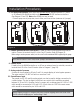
Phase Imbalance
Phase voltage imbalance of the input AC source can cause unbalanced currents and excessive
heat in the drive’s input rectifier diodes and DC bus capacitors. Phase imbalance can also damage
motors running directly across the line.
Step 9 - Terminals Found on the Power Board
Description of the Terminals
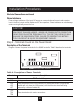
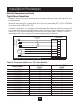
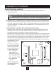
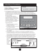
Diagram 4 shows the power terminals for the AQUAVAR controller. Table 8 describes the terminals.
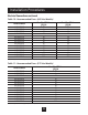
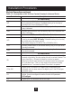
Table 8: Description of Power Terminals
Terminal Description
TB1 Terminal Group
GND Earth ground.
L1/R These terminals are the line connections for three-phase models. (Single-phase
L2/S models will only have the L1/R terminal, with the other two terminals being
L3/T replaced by a terminal labeled N.)
T1/U
T2/V These terminals are for motor connections.
T3W
Installation Procedures
21
CAUTION!
EQUIPMENT DAMAGE HAZARD - NEVER USE POWER-FACTOR CORRECTION
CAPACITORS ON MOTOR TERMINALS T1/U, T2/V OR T3/W. DOING SO WILL
DAMAGE THE SEMICONDUCTORS. FAILURE TO OBSERVE THIS INSTRUC-
TION CAN RESULT IN INJURY OR EQUIPMENT DAMAGE.
GND
L1/R
L2/S
L3/T
B–
B
+
DB
T1/U
T2/V
T3/W
GND
Diagram 4: AQUAVAR Controller Power Terminals