
User guide


Electrical Connections continued
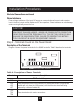
Typical Power Connections
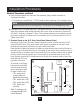
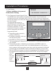
Diagram 5 shows the terminal connections for line power and motor output. See Step 8 for input
line requirements.
Note that when testing for a ground fault, do not short any motor lead (T1/U, T2/V or T3/W) back
to an input phase (L1/R, L2/S or L3/T).
As shown in Diagram 5, it is necessary to provide fuses and a disconnect switch for the input AC
line in accordance with all applicable electrical codes. The drive is able to withstand a 110% over
load for 60 s. For maximum protection of the drive, use the fuses listed in Tables 9, 10 and 11
found below and on the next page. The recommended supplier is Bussman.
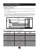
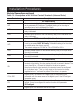
Table 9: Recommended Fuses (230 Vac Models)
Fuse Size 208 Vac Fuse Size 230 Vac
Model Number
JJS/JJN
1
JJS/JJN
1
AV2V2S010D 15 10
AV2V2S020D 20 20
AV2V2S030D 30 30
AV2V2S050D 45 45
AV2V2S075D 60 60
AV2V2S100D 80 80
AV2V20010D 10 6
AV2V20020D 15 10
AV2V20030D 20 15
AV2V20050D 30 25
AV2V20075D 40 35
AV2V20100D 50 40
AV2V20150D 70 60
AV2V20200D 70 60
(1) For sizes up to and including 30 A, KTK fuses may be substituted.
Installation Procedures
22
AV2V Drive
Motor
Fuses
Disconnect
Switch
Three-Phase
AC Power
L1/R
L2/S
L3/T
T1/U
T2/V
T3/W
GND
GND
Diagram 5: Connections for Power Wiring