Operating manual IQ SENSOR NET FDO® 70x IQ (SW) FDO® 700 IQ FDO® 701 IQ FDO® 700 IQ FDO® 701 IQ SW Optical IQ SENSOR NET D.O.
FDO® 70x IQ (SW) Note For the most recent version of the manual, please visit www.ysi.com. Contact Copyright 2 YSI 1725 Brannum Lane Yellow Springs, OH 45387 USA Tel: +1 937-767-7241 800-765-4974 Email: environmental@ysi.com Internet: www.ysi.com © 2012 Xylem Inc.
FDO® 70x IQ (SW) Contents FDO® 70x IQ (SW) - Contents 1 Overview . . . . . . . . . . . . . . . . . . . . . . . . . . . . . . . . . . . . 1-1 1.1 1.2 1.3 1.4 2 Safety . . . . . . . . . . . . . . . . . . . . . . . . . . . . . . . . . . . . . . 2-1 2.1 2.2 3 3.4 5.5 ba76014e01 02/2012 Measuring . . . . . . . . . . . . . . . . . . . . . . . . . . . . . . . . . . . 4-1 Function check and user calibration . . . . . . . . . . . . . . . . 4-1 4.2.1 General information . . . . . . . . . . . . . . . . . .
FDO® 70x IQ (SW) Contents 7 Technical data . . . . . . . . . . . . . . . . . . . . . . . . . . . . . . . 7-1 7.1 7.2 7.3 7.4 7.5 7.6 8 Contact Information . . . . . . . . . . . . . . . . . . . . . . . . . . . 8-1 8.1 8.2 9 Ordering & Technical Support . . . . . . . . . . . . . . . . . . . .8-1 Service Information . . . . . . . . . . . . . . . . . . . . . . . . . . . . .8-1 Indexes . . . . . . . . . . . . . . . . . . . . . . . . . . . . . . . . . . . . . 9-1 9.1 9.
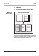
FDO® 70x IQ (SW) Overview 1 Overview 1.1 How to use this component operating manual Structure of the IQ SENSOR NET operating manual IQ Sensor Net Operating Manual System Operating Manual (Ring Binder) IQ Sensor Operating Manual MIQ Module Operating Manual MIQ Terminal Operating Manual Component Operating Manuals Fig. 1-1 Structure of the IQ SENSOR NET operating manual The IQ SENSOR NET operating manual has a modular structure like the IQ SENSOR NET system itself.
FDO® 70x IQ (SW) Overview 1.
FDO® 70x IQ (SW) Overview 1.3 Recommended fields of application Sensor model Recommended field of application. FDO® 700 IQ FDO® 701 IQ Stationary measurements in water/wastewater applications. FDO® 700 IQ SW FDO® 701 IQ SW Stationary measurements in seawater, aquaculture. The FDO® 70x IQ SW is equipped with a protective hood that is prepared for the connection of the MSK FDO® CS cleaning set for compressed air-driven sensor cleaning (order information, see section 5.
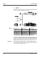
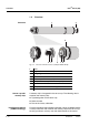
FDO® 70x IQ (SW) Overview 1.4 Structure 1 Structure 2 9 3 Fig. 1-2 Sensor cap with memory chip 4 5 6 7 8 Structure of the D. O. sensor (example: FDO® 70x IQ) 1 Shaft 2 Plug head connector 3 Fixing ring 4 Sensor membrane 5 Sensor cap with memory chip 6 Gold-plated contact pins for memory chip 7 Measurement window 8 Temperature sensor and locking device 9 Sensor head A memory chip is integrated in the sensor cap.
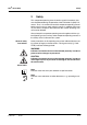
FDO® 70x IQ (SW) Safety 2 Safety This component operating manual contains special instructions that must be followed during the operation of the FDO® 70x IQ (SW) D.O. sensor. Thus, it is essential to read this component operating manual before carrying out any work using this sensor. In addition to this manual, the SAFETY chapter of the IQ SENSOR NET system operating manual must be followed.
FDO® 70x IQ (SW) Safety 2.1 Authorized use The authorized use of the FDO® 70x IQ (SW) comprises its use as a D.O. sensor in the IQ SENSOR NET. The technical specifications according to chapter 7 TECHNICAL DATA must be observed. Only operation according to the instructions in this operating manual is authorized. Any other use is considered to be unauthorized. Unauthorized use invalidates any claims with regard to the guarantee.
FDO® 70x IQ (SW) Safe operation Safety If safe operation is no longer possible, the sensor must be taken out of operation and secured against inadvertent operation. Safe operation is no longer possible if the sensor: has been damaged in transport has been stored under adverse conditions for a lengthy period of time is visibly damaged no longer operates as described in this manual. If you are in any doubt, contact the supplier of your sensor.
Safety 2-4 FDO® 70x IQ (SW) ba76014e01 02/2012
FDO® 70x IQ (SW) Commissioning 3 Commissioning 3.1 Scope of delivery Sensor, consisting of sensor basis and sensor cap Operating manual. 3.2 Connection cable Installation A sensor connection cable of the SACIQ or SACIQ SW type is required to connect the sensor. The cable is available in different lengths.
FDO® 70x IQ (SW) Commissioning Connecting the sensor to the sensor connection cable 1 Take the protective caps off the plug connections of the sensor and the SACIQ (SW) sensor connection cable and keep them safe. 2 Plug the jack of the SACIQ (SW) sensor connection cable onto the plug head connector of the sensor. At the same time, rotate the socket so that the pin in the plug head connector (1) clicks into one of the two holes in the socket.
FDO® 70x IQ (SW) Commissioning 3.3 Identification in the IQ SENSOR NET Commissioning steps ba76014e01 02/2012 Commissioning / Getting the instrument ready for measuring Both the sensor cap and sensor basis (sensor without cap) have a series number of their own. The sensor has to be equipped with a sensor cap for a successful login to the IQ SENSOR NET. The operable sensor is displayed as follows in the list of sensors: Model: Model designation of the sensor cap (="SC FDO 70x") Ser. no.
FDO® 70x IQ (SW) Commissioning 3.4 FDO® 70x IQ (SW) setting table Setting Selection/values Explanation Measuring mode Concentration Unit of the measured value on the measured value display. Saturation Measuring range Concentration 0 ... 20.00 mg/l 0 ... 20.00 ppm These measuring ranges are available for selection. Measuring range Saturation 0 ... 200.0 % The measuring range is set permanently. Response time t90 150 .. 300 s Response time of the signal filter.
FDO® 70x IQ (SW) Commissioning Setting Selection/values Explanation Temp. adjustment -1.5 K ... +1.5 K The temperature compensation enables the temperature display to be balanced (shifting of the zero point by ±1.5K). Notes: Due to the thermal capacity of the sensor, it is necessary to place it in a container with at least 2 liters of water. Leave the sensor in this container for at least 15 minutes while stirring occasionally until the balancing can be performed.
Commissioning 3-6 FDO® 70x IQ (SW) ba76014e01 02/2012
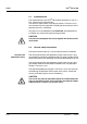
FDO® 70x IQ (SW) Measuring / Operation 4 Measuring / Operation 4.1 Measuring WARNING Contact with the sample can be dangerous for the user! Depending on the type of sample, suitable protective measures must be taken (protective clothing, protective goggles, etc.). Note the data given in section 7.2 APPLICATION CONDITIONS, especially the minimum immersion depth of the sensor (> 50 mm). The measured value is available immediately on submersing.
FDO® 70x IQ (SW) Measuring / Operation 2 cm With air temperatures under 5 °C we recommend performing the function check and user calibration not in air but in air-saturated water that has a higher temperature. You obtain air-saturated water by pouring water several times in and out of two vessels so that it sparkles. 4.2.2 Function check A function check is the simplest way to determine whether the sensor needs to be cleaned or user-calibrated.
FDO® 70x IQ (SW) Canceling the check Measuring / Operation 6 Press g. The sensor starts the check. The display switches to the measured value display. The CAL indicator flashes instead of the main measured value. At the same time, the momentary relative slope flashes as the secondary measured value with the addition of TEST. The process ends automatically as soon as the measured values meet the criterion for the stability control.
FDO® 70x IQ (SW) Measuring / Operation 4.2.3 Principle User calibration The user calibration can either be done in water vapor-saturated air or in air-saturated water (see CHECK OR CALIBRATION MEDIUM on page 4-1). With the calibration procedure, the relative slope of the sensor is determined. The calibration is evaluated based on the relative slope and the intensity (successful <-> unsuccessful).
FDO® 70x IQ (SW) Canceling the user calibration Measuring / Operation 8 Wait for the measured value to be largely stable (temperature adjustment). 9 Switch off the maintenance condition. As long as the determination of the calibration data has not yet been started (step 6), you can quit the calibration routine with m or e. The running determination of calibration data (after pressing g in step 6) can be aborted as follows: 1 Open the setting table (see section 3.4).
FDO® 70x IQ (SW) Measuring / Operation 4.2.4 Calibration history Calibration history (available in the IQ SENSOR NET system 2020 XT only) Currently active calibration Chronological list of the last user calibrations Fig. 4-1 Calibration historyFDO® 70x IQ (SW) The calibration history contains the following information: Date Calibration date (Factory = factory calibration) Rel.slope Relative slope (non-dimensional) Intens.
FDO® 70x IQ (SW) Measuring / Operation 4.2.5 Reactivating previous calibration data The FDO® 70x IQ (SW) enables you to reactivate the last valid user calibration or the factory calibration. Thus you can immediately go on measuring if a calibration procedure failed or you suspect that the calibration conditions were not optimally met. Note Reactivating old calibration data is only a temporary solution. Please take into account that the sensor might thus possibly provide incorrect measured values.
Measuring / Operation 4-8 FDO® 70x IQ (SW) ba76014e01 02/2012
FDO® 70x IQ (SW) Maintenance, cleaning, replacement parts 5 Maintenance, cleaning, replacement parts 5.1 General maintenance instructions WARNING Contact with the sample can be dangerous for the user! Depending on the type of sample, suitable protective measures must be taken (protective clothing, protective goggles, etc.). Maintenance condition We recommend to switch on the maintenance condition each time the sensor is taken out of the measuring position.
Maintenance, cleaning, replacement parts 5.2 FDO® 70x IQ (SW) Handling of the sensor cap Despite its exterior robustness, the sensor is an optical high precision instrument. Therefore, special care should be taken when doing any maintenance or cleaning work: Dirt and moisture under the sensor cap can affect the functioning and shorten the service life of the sensor cap. Therefore, make sure the working environment is clean and dry prior to removing the sensor cap.
FDO® 70x IQ (SW) Mounting the sensor cap Maintenance, cleaning, replacement parts 6 Check the front surface of the sensor for absolute cleanness and clean it if necessary (see section 5.4.1). 7 Thoroughly clean the thread of the fixing ring. 8 Place the new sensor cap on the sensor so that the temperature sensor fits into the hole inside the sensor cap (see figure opposite). 9 Put the fixing ring on the sensor head and screw it tight by hand. 5.4 Cleaning the sensor 5.4.
Maintenance, cleaning, replacement parts 5.4.2 FDO® 70x IQ (SW) Interior cleaning of sensor cap and sensor head If moisture or dirt have penetrated under the sensor cap, e.g. because the sensor cap is damaged, you can make the sensor ready for operation again as follows: Caution Only use nonabrasive, alcohol-free detergents, as otherwise the optical surfaces could be damaged. 1 Remove the sensor cap (see section 5.3).
FDO® 70x IQ (SW) Maintenance, cleaning, replacement parts 5.5 Replacement parts and accessories Description Model Order no.
Maintenance, cleaning, replacement parts 5-6 FDO® 70x IQ (SW) ba76014e01 02/2012
FDO® 70x IQ (SW) What to do if... 6 What to do if... Sensor does not appear in the measured value display and list of sensors Cause Remedy – Sensor cap not mounted or defective – Sensor cap (see section 5.3) Measured value implausible Cause Remedy – Coating on sensor cap – Clean the outside of the sensor (see section 5.4.1) – Service life of the sensor cap over – Check the sensor (see section 4.2.
FDO® 70x IQ (SW) What to do if... Measured value invalid ( "----" displayed) Cause Remedy – User calibration unsuccessful. The sensor is blocked for measurement. – As a temporary measure to quickly restore the readiness for service: Activate the factory calibration (see section 4.2.5) – For exact measurements, carry out a function check and repeat the user calibration if necessary.
FDO® 70x IQ (SW) Technical data 7 Technical data 7.1 General measurement characteristics Note The measurement characteristics are primarily determined by the sensor cap type. The relevant data are given in the sections 7.5 and 7.6. Measuring principle Measurement in water Measurement in saltcontaminated wastewater Temperature measurement Temperature compensation Optical measurement based on photoluminescence. According to solubility function according to ISO 5814 Salinity input from 2.0 ... 70.
FDO® 70x IQ (SW) Technical data 7.3 Dimensions General data FDO 70x IQ: 400 40.0 39.7 Socket SACIQ... FDO 70x IQ SW: 400 34 276 39.7 Weight (without sensor connection cable) Connection technique Material Socket SACIQ... 59.5 FDO® 70x IQ Approx. 900 g FDO® 70x IQ SW Approx. 1500 g Connection via SACIQ (SW) sensor connection cable Shaft: – FDO® 70x IQ ® – FDO 70x IQ SW V4A stainless steel 1.4571 * POM Plug head connector housing POM Sensor head POM and PVC Sensor cap See section 7.
FDO® 70x IQ (SW) Automatic sensor monitoring (SensCheck function) Instrument safety Technical data Monitoring of the membrane function Applicable norms – EN 61010-1 – UL 3111-1 – CAN/CSA C22.2 No. 1010.1 7.4 ba76014e01 02/2012 Electrical data Nominal voltage Max. 24VDC via the IQ SENSOR NET (for more details, see chapter TECHNICAL DATA of the IQ SENSOR NET system operating manual) Power consumption 0.
FDO® 70x IQ (SW) Technical data 7.5 Measuring ranges and resolutions Measurement accuracy Repeatability Response time Minimum approach flow Interferences Allowed temperature range Allowed pH range of the test sample Calibration procedure Material Working life 7-4 Technical data of the SC-FDO® 700 D. O. partial pressure 0 ... 400 hPa Measuring mode Adjustable measuring range Resolution D. O. concentration 0 ... 20.00 mg/L 0 ... 20.00 ppm 0.01 mg/L 0.01 ppm D. O. saturation 0 ... 200.0 % 0.
FDO® 70x IQ (SW) Technical data 7.6 Measuring ranges and resolutions Measurement accuracy Repeatability Response time Minimum approach flow Interferences Allowed temperature range Allowed pH range of the test sample Calibration procedure Material Working life ba76014e01 02/2012 Technical data of the SC-FDO® 701 D. O. partial pressure 0 ... 400 hPa Measuring mode Adjustable measuring range Resolution D. O. concentration 0 ... 20.00 mg/L 0 ... 20.00 ppm 0.01 mg/L 0.01 ppm D. O.
Technical data 7-6 FDO® 70x IQ (SW) ba76014e01 02/2012
FDO® 70x IQ (SW) Contact Information 8 Contact Information 8.1 Ordering & Technical Support Telephone: (800) 897-4151 (937) 767-7241 Monday through Friday, 8:00 AM to 5:00 PM ET Fax: (937) 767-1058 Email: environmental@ysi.com Mail: YSI Incorporated 1725 Brannum Lane Yellow Springs, OH 45387 USA Internet: www.ysi.com When placing an order please have the following information available: YSI account number (if available) Model number or brief description Quantity 8.
Contact Information 8-2 FDO® 70x IQ (SW) ba76014e01 02/2012
FDO® 70x IQ (SW) Indexes 9 Indexes 9.1 Explanation of the messages This chapter contains a list of all the message codes and related message texts that can occur in the log book of the IQ SENSOR NET system for the FDO® 70x IQ (SW) sensor. Note Information on the contents and structure of the log book, and how to call it up, is given in the LOG BOOK chapter of the IQ SENSOR NET system operating manual.
FDO® 70x IQ (SW) Indexes Message code Message text EC833x Sensor could not be calibrated, sensor blocked for measurement Cause: instable signal * Check temperature adjustment * Check calibration conditions (see operating manual) * Repeat calibration EC933x Calibration error, measurement disabled Cause: Sensor cap is missing, leaky, depleted, or defective * Clean sensor and space between cap and sensor according to op.
FDO® 70x IQ (SW) Indexes 9.1.2 Info messages Message code Message text IC133x Sensor has been successfully calibrated * For calibration data, see calibration history IC333x Factory calibration has been activated. Make sure the sensor operates correctly. IC433x Last valid user calibration has been activated. Make sure the sensor operates correctly. IC533x Invalid user calibration has been replaced by last valid user calibration. Caution! Wrong measured values possible.
FDO® 70x IQ (SW) Indexes 9.2 Status info The status info is a coded piece of information on the current status of a sensor. Each sensor sends this status info to the controller. The status info of sensors consists of 32 bits, each of which can have the value 0 or 1.
1725 Brannum Lane Yellow Springs, Ohio 45387 USA +1 937-767-7241 800-765-4974 (US) FAX (937) 767-1058 Email: environmental@ysi.com Internet: www.ysi.