MICRO-FLO MICRO-FLO Digital Paddlewheel Flow meter Operating Manual Blue-White R Industries, Ltd. 5300 Business Drive Huntington Beach, CA 92649 USA Phone: 714-893-8529 FAX: 714-894-9492 E mail: sales@blue-white.com or techsupport@blue-white.com Website: www.blue-white.
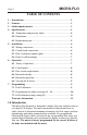
Page 2 MICRO-FLO TABLE OF CONTENTS 1.....Introduction....................................................................................2 2.....Features ..........................................................................................3 3.....Model number matrix ....................................................................3 4.....Specifications ..................................................................................4 4.1..Temperature and pressure limits...........................
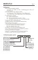
MICRO-FLO Page 3 2.0 Features ! Four connection options available: 1/8” F/NPT, 1/4” F/NPT, 1/4” OD x .170 ID Tubing & 3/8” OD x 1/4” ID Tubing sizes. ! Six body size/flow range options available: 30 to 300 ml/min, 100 to 1000 ml/min, 200 to 2000 ml/min, 300 to 3000 ml/min, 500 to 5000 ml/min, 700 to 7000 ml/min. ! 3 model display variations: FS = Sensor mounted display FP = Panel mounted display (includes 6’ cable) FV = No display. Sensor only.
MICRO-FLO Page 4 4.0 Specifications Max. Working Pressure: PVC lens, PVDF lens, Max.
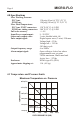
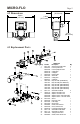
MICRO-FLO Page 5 2.22 in [56.26 mm] 4.2 Dimensions 5.00 in [127 mm] 1.48 in [37.71 mm] 3.51 in [89.03 mm] 18 4.3 Replacement Parts 16 20 13 17 15 10 Key 1 2 14 22 4 5 6 8 7 9 6 7 8 9 8 5 4 2 3 21 1 10 13 14 15 16 17 18 19 20 21 22 Part No.
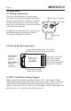
MICRO-FLO Page 6 5.0 Installation 5.1 Wiring Connections On sensor mounted units, the output signal wires must be installed through the back panel using a second liquid-tite connector (included). To install the connector, remove the circular knock-out. Trim the edge if required. Install the extra liquid-tite connector. On panel or wall mounted units, wiring may be installed through the enclosure bottom or through the back panel. See below. KNOCK-OUT ½” diameter Power Input Rear view 5.
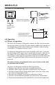
MICRO-FLO Page 7 5.4 Panel or wall mounting Wiring through enclosure bottom for dry applications Panel or wall mounting screw locations Through panel wiring for water resistant applications 1.75 in [45 mm] Recommended panel or wall mounting cut-out for wire connection opening 1.00 in [25 mm] 6.0 Operation 6.1 Theory of operation The Micro-Flo flowmeter is designed to measure the flow rate and accumulate the total volume of a fluid.
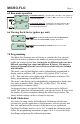
MICRO-FLO Page 8 6.2 Control Panel Enter Button (right arrow) ! Press and release - Toggle between Rate, Total, and Calibrate screens in the run mode. Select program screens in the program mode. ! Press and hold 2 seconds - Enter and exit program mode. (Automatic exit program mode after 30 seconds of no inputs). Clear/Cal (up arrow) ! Press and release - Clear total in the run mode. Scroll through and Select options in the program mode. 6.
MICRO-FLO Page 9 6.5 Run mode operation S1 ML R ENTER Min S1 ML T ENTER 0 FLOW RATE DISPLAY - Indicates rate of flow, S1 = body size/range #1, ML = units displayed in milliliters, MIN = time units in minutes, R = flow rate displayed. 0 FLOW TOTAL DISPLAY - Indicates accumulated total flow, S1 = body size/range #1, ML = units displayed in milliliters, T = total accumulated flow displayed. 6.
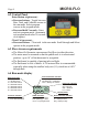
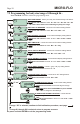
MICRO-FLO Page 10 7.2 Programming for body size/ranges S1through S6 Press and Hold ENTER to initiate the programming mode. S1 BODY SIZE/RANGE - Select your body size. Selected body size flashes. CLEAR CAL / ENTER 1 ENTER R ML R 0 Min ML 0 T 2 ENTER 0 Min 1 ENTER ML R 3 ENTER 0 Min 2 ENTER ML ML 0 T 3 ENTER RST T 1 ENTER ENTER If “off” R SetP Y off 2 If “on” Press and release to select.
MICRO-FLO Page 11 7.3 Field calibration size/range setting S0 - Continuation of programming sequence when range “S0” is selected. The meter should be installed as intended in the application. The amount of fluid that flows through the meter during the calibration procedure must be measured at the end of the calibration procedure. Allow the meter to operate normally, in the intended application, for a period of time. A test time of at least one minute is recommended. Pulses will accumulate in the display.
BLUE-WHITE INDUSTRIES LIMITED WARRANTY FLOWMETERS are warranted to be free of defects in material and workmanship for up to 12 months from the date of factory shipment. Warranty coverage is limited to repair or replacement of the defective flowmeter only. Blue-White Industries does not assume responsibility for any other damage that may occur.