
Instruction Manual

1
2
3
4
5
6
7
8
21
9
10
14
15
13
19
20
16
17
18
22
8
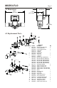
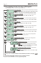
PARTS LIST
Key Part No. Description Qty.
1 90011-081 Screw 6-32x.50 Phil Flt SS 4
2 90002-227 Lens Cap Clear PVC 1
90002-228 Lens Cap Opaque PVDF 3
90003-143 O-Ring Viton 1
90003-146 O-Ring EP
4 90002-230 Paddle PVDF 1
5 90007-592 Axle PVDF 1
6 90003-012 O-Ring Viton 2
90003-011 O-Ring EP
7 76001-300 Body S1 PVDF (30-300ml/min) 1
76001-301 Body S2 PVDF(100-1000ml/min)
76001-302 Body S2 PVDF (200-2000ml/min)
76001-303 Body S2 PVDF (300-3000ml/min)
76001-304 Body S2 PVDF (500-5000ml/min)
76001-305 Body S2 PVDF (700-7000ml/min)
8 90011-113 Screw #4x.50 Phil Blk 4
9 76000-137 Adapter .250 F/NPT PVC 2
76000-456 Adapter .125 F/NPT PVC
90002-038 Adapter .37OD x .25ID Tube PVDF
90002-042 Adapter .25OD x .17ID Tube PVDF
10 90012-252 Sensor 1
13 90002-242 Enclosure, Valox 1
14 90012-254 LCD display 1
15 90010-260 Circuit board 1
16 90006-604 Gasket, rear enclosure 1
17 90002-243 Cover, enclosure rear 1
18 90008-199 Liquid Tight Connector Set 1
19 90011-178 Screw #4x.62 Phil SS Blk 4
20 90011-177 Screw #2x.25 L Phil St 2
21 76001-299 Tubing connector seal 1
22 90006-605 Gasket, sensor mount seal 1
Page 5MICRO-FLO
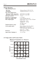
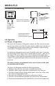
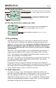
5.00 in
[127 mm]
3.51 in
[89.03 mm]
1.48 in
[37.71 mm]
2.22 in
[56.26 mm]
4.2 Dimensions
4.3 Replacement Parts