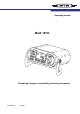
Operating manual Multi 1970i ON / O M CAL AUTO RUN / OFF READ ENTE 792 mg/ l 176° C R ARng RCL TP REL1 STO Multi 1970 i Portable pH / oxygen / conductivity measuring instrument ba75693e01 01/2007
Accuracy when going to press Copyright The use of advanced technology and the high quality standard of our instruments are the result of a continuous development. This may result in differences between this operating manual and your instrument. Also, we cannot guarantee that there are absolutely no errors in this manual. Therefore, we are sure you will understand that we cannot accept any legal claims resulting from the data, figures or descriptions.
Multi 1970i List of contents 1 Overview . . . . . . . . . . . . . . . . . . . . . . . . . . . . . . . . . . . . . 3 1.1 1.2 1.3 1.4 2 Authorized use . . . . . . . . . . . . . . . . . . . . . . . . . . . . . . . . . 9 General safety instructions . . . . . . . . . . . . . . . . . . . . . . . 10 Commissioning . . . . . . . . . . . . . . . . . . . . . . . . . . . . . . . 11 3.1 3.2 3.3 3.4 4 3 4 5 5 Safety . . . . . . . . . . . . . . . . . . . . . . . . . . . . . . . . . . . . . . . . 9 2.1 2.
List of contents Multi 1970i 4.8.1 Data transmission interval (Int 2) . . . . . . . . . . . . 4.8.2 PC/external printer (RS232 interface) . . . . . . . . 4.8.3 Remote control . . . . . . . . . . . . . . . . . . . . . . . . . 4.9 Configuration . . . . . . . . . . . . . . . . . . . . . . . . . . . . . . . . . 4.10 Reset . . . . . . . . . . . . . . . . . . . . . . . . . . . . . . . . . . . . . . . 5 Maintenance, cleaning, disposal . . . . . . . . . . . . . . . . . 65 5.1 5.2 5.3 6 2 pH system messages .
Multi 1970i Overview 1 Overview 1.1 General features The Multi 1970i portable multiparameter measuring instrument enables you to carry out pH measurements, dissolved oxygen (D. O.) measurements and conductivity measurements quickly and reliably. The Multi 1970i provides the maximum degree of operating comfort, reliability and measuring certainty for all applications.
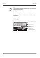
Overview Multi 1970i Note If you need further information or application notes, you can obtain the following material from WTW: z Application reports z Primers z Safety datasheets. You will find information on available literature in the WTW catalog or via the Internet. 1.2 Display Status display indicator pH S O Sal Time 1888 Baud Day.Month Year No.
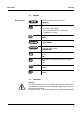
Multi 1970i Overview 1.3 Key functions Keypad ON / OFF Switch measuring instrument on/off Select the measured variable : – pH value / ORP voltage M – D. O. concentration / D. O.
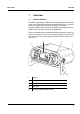
Overview Multi 1970i Maximum number of sensors to be connected The following sensors can be connected to the Multi 1970i (maximum configuration): z One pH depth armature or one pH electrode (combination electrode or pH electrode + reference electrode). Please make sure that only one pH sensor is connected at the same time. z One D. O.
Multi 1970i Overview Note The sensor sockets, 1 and 2 must not be assigned at the same time. On the two sockets, 5 and 6, only different sensor types (Oxi and Cond) may be connected at the same time.
Overview 8 Multi 1970i
Multi 1970i Safety 2 Safety This operating manual contains basic instructions that you must follow during the commissioning, operation and maintenance of the measuring instrument. Consequently, all responsible personnel must read this operating manual before working with the measuring system. The operating manual must always be available within the vicinity of the measuring system. Target group The measuring instrument was developed for work in the field and in the laboratory.
Safety Multi 1970i 2.2 General safety instructions This instrument is built and inspected according to the relevant guidelines and norms for electronic measuring instruments (see chapter 7 TECHNICAL DATA). It left the factory in a safe and secure technical condition.
Multi 1970i Commissioning 3 Commissioning 3.1 Scope of delivery z Multi 1970i portable multiparameter measuring instrument with integrated rechargeable battery z Carrying and positioning handle z Carrying strap z 2 sensor quivers (pH and Oxi-LF type) z Plug-in power supply unit z Operating manual 3.2 Power supply Mains operation and charging the battery You can either operate the measuring instrument with the integrated rechargeable battery or with the plug-in power supply.
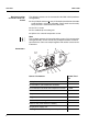
Commissioning Multi 1970i Connecting the plug-in power supply unit 2 1 3 1 Connect the plug (1) to the socket (2) of the measuring instrument. 2 Connect the original WTW plug-in power supply (3) to an easily accessible mains socket. 3.3 Initial commissioning Perform the following activities: z For mains operation and charging the battery: Connect the plug-in power supply (see section 3.2 POWER SUPPLY). z Set the date and time. Setting the date and time 12 1 Press the key and hold it down.
Multi 1970i Commissioning pH S O Sal Time It 25 Baud Day.Month Year No. Ident Tref25 LoBat nLF 090 Tref20 Lin Oxi Auto Store Cal TEC mV/ pH % mg/l mS/cm 1/cm Sal 4 °C% / K ARng TP REL1 REL2 AR RCL 4 Set the date of the current day with <▲> <▼>. 5 Confirm with . The date (month) flashes in the display. 6 Set the current month with <▲> <▼>. 7 Confirm with . The year appears on the display. 8 Set the current year with <▲> <▼>. 9 Confirm with .
Commissioning Multi 1970i 3.4 Sensor quiver To store the sensors during field operation and to keep the sensor element moist, the quiver tip contains a sponge rubber insert that can be moistened with deionized water. Note For further details on proper storage, refer to the operating manual of the sensor. Moistening the quiver insert 1 Press the quiver out of the holder from the back side of the instrument and pull it out completely.
Multi 1970i Active and inactive REL socket Operation 4 Operation 4.1 Operating structure In addition to the pH/ORP sensor, the sensor on the REL1 or REL2 socket can be actuated (switched "active"). The other socket is not actuated ("inactive"). This switching over inside the instrument is made with the aid of a relay. The active REL socket is shown on the display.
Operation Multi 1970i Note When a sensor is connected to the active REL socket, the measuring instrument recognizes the sensor or the measuring cell and automatically switches to the measuring mode that was last active. As soon as the sensor is disconnected from the active REL socket, the instrument switches to the pH (mV) measuring mode again. 4.2 1 Measuring mode when switching on Switching on the measuring instrument Press the key. The display test appears briefly on the display.
Multi 1970i Preparatory activities Operation 4.3 pH value / ORP voltage 4.3.1 General information Perform the following preparatory activities when you want to measure: 1 Connect the pH depth armature or the pH electrode to the measuring instrument. If necessary, press the key repeatedly until the pH (pH measurement) or U (measurement of the ORP voltage) display appears.
Operation Temperature measurement in pH measurements Multi 1970i You can perform pH measurements with or without a temperature sensor as well as with the temperature sensor of an oxygen sensor or a conductivity measuring cell. The measuring instrument recognizes which sensors are connected and switches automatically to the correct mode for the temperature measurement. The following cases are distinguishable.
Multi 1970i Operation 4.3.2 Measuring the pH value 1 Perform the preparatory activities according to section 4.3.1. 2 Immerse the pH electrode in the test sample. 3 Press the <▲> <▼> keys repeatedly until pH appears on the status display. The pH value appears on the display. pH S O Sal Time 1699 Baud Day.Month Year No.
Operation Multi 1970i 2 Activate the AutoRead function with . The current measured value is frozen (hold function). 3 Start AutoRead with . AR flashes until a stable measured value is reached. This measured value is transmitted to the interface. 4 If necessary, start the next AutoRead measurement with . 5 To terminate the AutoRead function: Press the key.
Multi 1970i Operation 4.3.4 Why calibrate? When to calibrate? pH calibration pH electrodes age. This changes the asymmetry (zero point) and slope of the pH electrode. As a result, an inexact measured value is displayed. Calibration determines the current values of the asymmetry and slope of the electrode and stores them in the measuring instrument. Thus, you should calibrate at regular intervals. z After connecting another electrode z When the sensor symbol flashes, i.e.
Operation Multi 1970i Note You can automatically print a calibration protocol after the calibration. To do so, connect a printer to the interface according to section 4.8.2 before calibrating. After a valid calibration, the record is printed. Sample printout: CALIBRATION PROTOCOL 02.03.02 14:19 Device No.: 12345678 Calibration pH Cal time: 01.03.01 / 15:20 Cal interval: 7d AutoCal TEC Tauto Buffer 1 2.00 Buffer 2 4.01 Buffer 3 7.00 * Buffer 4 10.01 C1 184.1 mV 25.0°C C2 3.0 mV 25.0°C S1 -59.
Multi 1970i Calibration evaluation Operation After calibrating, the measuring instrument automatically evaluates the calibration. The asymmetry and slope are evaluated separately. The worst evaluation appears on the display. Display Asymmetry [mV] Slope [mV/pH] -15 ... +15 -60.5 ... -58 -20 ... +20 -58 ... -57 -25 ... +25 -61 ... -60.5 or -57 ... -56 -30 ... +30 -62 ... -61 or -56 ...
Operation Multi 1970i AutoCal TEC For this procedure, use any two WTW technical buffer solutions (pH values at 25 °C: 2.00 / 4.01 / 7.00 / 10.01). Note The calibration for pH 10.01 is optimized for the WTW technical buffer solution TEP 10 Trace or TPL 10 Trace. Other buffer solutions can lead to an erroneous calibration. The correct buffer solutions are given in the WTW catalog or in the Internet. Note The buffer solutions are automatically recognized by the measuring instrument.
Multi 1970i Operation pH S O Sal Time 1693 Baud Day.Month Year No. Ident Tref25 LoBat nLF 5 824 Tref20 Lin Oxi Auto Cal TEC Baud No. Ident Tref25 LoBat 8 °C% / K ARng 1C T 2 Day.Month Year 1/cm Sal TP pH S O Sal Time REL2 AR RCL Baud Day.Month Year REL1 1700 No. Ident Tref25 LoBat nLF 824 Tref20 Lin Oxi Auto Cal TEC mV/ pH % mg/l mS/cm 1/cm Sal 8 °C% / K ARng TP REL1 REL2 AR RCL When the measured value is stable, Ct2 appears.
Operation Multi 1970i pH S O Sal Time 1184 Baud Day.Month Year No. Ident Tref25 LoBat nLF 10 824 Tref20 Lin Oxi Auto Cal TEC ARng 1594 Baud No. Ident Tref25 LoBat nLF 11 824 Tref20 Lin Oxi Auto Store Cal TEC Baud No. Ident Tref25 LoBat 12 26 REL2 AR RCL 1401 Baud Day.Month Year REL1 No. Ident Tref25 LoBat nLF 824 Tref20 Lin Oxi Auto Cal TEC 1/cm Sal 8 °C% / K ARng TP REL1 REL2 AR RCL mV/ pH % mg/l mS/cm 1/cm Sal 8 °C% / K ARng 1592 Day.
Multi 1970i Operation 4.4 Dissolved oxygen 4.4.1 General information Note D. O. measurements with the Multi 1970i can only be carried out using a CellOx 325 or StirrOx G D. O. sensor. The stirrer of the StirrOx G D. O. sensor has to be supplied with voltage separately using the NT/pH Mix 540 power supply. You can measure the following variables: z D. O.
Operation Multi 1970i Note Incorrect calibration of D. O. probes will result in incorrect measured values. Calibrate at regular intervals. Temperature sensor 28 The D. O. sensor has an integrated temperature sensor that always measures the current temperature of the test sample.
Multi 1970i Operation 4.4.2 Measuring the D. O. concentration When measuring the concentration of test samples with a salt content of more than 1 g/l, a salinity correction is required. Note How to enter the current salt content is described in section 4.4.6 ENTERING THE SALT CONTENT (SALINITY) on page 35. Switching the salt content correction on or off, see below. To measure the D. O.
Operation Multi 1970i pH S O Sal Time 1542 Baud Day.Month Year No. Ident Tref25 LoBat nLF 4 817 Tref20 Lin Oxi Auto Store Cal TEC mV/ pH % mg/l mS/cm 1/cm Sal 6 °C% / K ARng TP REL1 REL2 AR RCL While pressing the key, switch off the salt content correction with <▼>. The SAL display indicator is no longer displayed. 4.4.3 Measuring the D. O. saturation You can measure the D. O. saturation as follows: 1 Perform the preparatory activities according to section 4.4.1.
Multi 1970i Operation 4.4.4 AutoRead AR (Drift control) and hold function The AutoRead function (drift control) checks the stability of the measurement signal. The stability has a considerable impact on the reproducibility of the measured values. With the aid of the hold function the measured value display is frozen. Criteria With identical measurement conditions, the following criteria are valid for the AutoRead function: Measuring mode Reproducibility Response time D. O.
Operation Multi 1970i 4.4.5 Why calibrate? When to calibrate? D. O. calibration D. O. probes age. This changes the slope of the D. O. sensor. Calibration determines the current slope of the sensor and stores this value in the instrument. z After connecting another D. O. sensor z When the sensor symbol flashes (after the calibration interval has expired).
Multi 1970i Sensor evaluation Operation After the calibration, the measuring instrument evaluates the current status of the sensor against the relative slope. The evaluation appears on the display. The relative slope has no effect on the measuring accuracy. Low values indicate that the electrolyte will soon be depleted and the sensor will have to be regenerated. Display Relative slope S = 0.8 ... 1.25 S = 0.7 ... 0.8 S = 0.6 ... 0.7 E3 Perform error elimination according to chapter 6 WHAT TO DO IF...
Operation Multi 1970i pH S O Sal 1C AL Time Baud Day.Month Year No. Ident Tref25 LoBat nLF 5 817 Tref20 Lin Oxi Auto Store Cal TEC ARng 1088 Baud No. Ident Tref25 LoBat nLF 6 Tref20 Lin Oxi Auto Store Cal TEC 7 RCL mV/ pH % mg/l mS/cm 1/cm Sal ARng 1088 Baud No. Ident Tref25 LoBat REL2 AR TP REL1 REL2 AR RCL As soon as a stable value is achieved the AR display stops flashing. The calibration is finished then.
Multi 1970i Operation 4.4.6 Entering the salt content (salinity) A salt content correction is required in the oxygen concentration measurement of samples with a salt content of more than 1 g/l. To do this, you have to enter the salinity equivalent (the measured salinity) of the test sample (range 0.0 - 70.0) and to switch on the salinity correction. Note With the Multi 1970i, you can measure the salinity. How to proceed is described in section 4.5.3 MEASURING THE SALINITY on page 38.
Operation Multi 1970i 4.5 Conductivity 4.5.1 General information Note Conductivity measurements with the Multi 1970i can only be carried out using the TetraCon 325 measuring cell. Warning When connecting an earthed PC/printer, measurements cannot be performed in earthed media as incorrect values would result. The RS232 interface is not galvanically isolated. The measuring instrument is supplied with the following functions: z AutoRange (automatic switchover of the measurement range).
Multi 1970i Operation Temperature compensation The nonlinear temperature compensation is set fixed and is shown on the display by nLF. Reference temperature, Tref The reference temperature (Tref) can be switched between 20 °C and 25 °C. It appears on the display as Tref20 or Tref25. To switch over the reference temperature, see SWITCHING OVER THE REFERENCE TEMPERATURE, page 60. Checking the cell constant 1 Press the key repeatedly until CAL disp appears on the display.
Operation Multi 1970i 4.5.2 Measuring the conductivity You can carry out the conductivity measurements as follows: 1 Perform the preparatory activities according to section 4.5.1 page 36. 2 Immerse the conductivity measuring cell in the test sample. 3 Press the < ▲> <▼> keys until in the status display, and the unit µS/cm appears. The conductivity value appears on the display. pH S O Sal Time C 530 Baud Day.Month Year No. Ident Tref25 LoBat nLF 4.5.
Multi 1970i Operation 4.5.4 AutoRead AR (Drift control) and hold function The AutoRead function (drift control) checks the stability of the measurement signal. The stability has a considerable impact on the reproducibility of the measured values. With the aid of the hold function the measured value display is frozen. For conductivity measurements, use the AutoRead function and hold function like this: 1 Call up the measuring mode <▼>. 2 Immerse the conductivity measuring cell in the test sample.
Operation Multi 1970i 4.5.5 Why determine the cell constant? Determining the cell constant (Calibration in the control standard) Aging slightly changes the cell constant, e. g. by coatings. As a result, an inexact measured value is displayed. The original characteristics of the cell can often be restored by cleaning the cell. Calibration determines the current value of the cell constant and stores this value in the instrument. Thus, you should calibrate at regular intervals.
Multi 1970i Calibration evaluation Operation After the calibration, the measuring instrument automatically evaluates the current status of the calibration. The evaluation appears on the display. Cell constant [cm-1] Display 0.450 ... 0.500 cm-1 Outside the range 0.450 ... 0.500 cm-1 E3 Perform error elimination according to chapter 6 WHAT TO DO IF...
Operation Multi 1970i 4 Press the key. The AutoRead measurement to determine the cell constant starts. The AR display indicator flashes until a stable signal is reached. The cell constant determined is displayed. The measuring instrument automatically stores the cell constant. pH S O Sal Time C C AL Baud Day.Month Year No.
Multi 1970i Operation 4.6 Calibration intervals (Int 3, Int 4, Int 5) For each measured variable, a time interval is stored. When it has expired, you will be reminded to calibrate. After a calibration interval has expired, the sensor symbol of the relevant measured variable flashes. It is still possible to measure. By calibrating the relevant sensor, the function is reset and the interval starts anew.
Operation Multi 1970i 4.7 Saving data The portable Multi 1970i multiparameter measuring instrument has an internal data storage. It can store up to 500 datasets.
Multi 1970i Operation pH S O Sal Time I699 Baud Day.Month Year No. Ident Tref25 LoBat Message StoFull nLF d41 Tref20 Lin Oxi Auto Store Cal TEC mV/ pH % mg/l mS/cm 1/cm Sal 2 °C% / K TP REL1 REL2 AR RCL ARng 3 Using <▲> <▼>, enter the required ID number (1 ... 999). 4 Confirm with . The measured values are stored. The instrument changes to the measuring mode. This message appears when all of the 500 storage locations are occupied.
Operation Multi 1970i 4.7.2 Switching on AutoStore (Int 1) The save interval (Int 1) determines the chronological interval between automatic save processes. After the fixed interval has expired, the current data record is transmitted to the internal storage and to the interface. Switching on AutoStore 1 Press the key and hold it down. 2 Press the key. Int 1 appears on the display. pH S O Sal Time Int 1 Baud Day.Month Year No.
Multi 1970i Operation pH S O Sal Time I499 Baud Day.Month Year No. Ident Tref25 LoBat nLF FRE Tref20 Lin Oxi Auto Store Cal TEC mV/ pH % mg/l mS/cm 1/cm Sal 1 °C% / K ARng TP REL1 REL2 AR RCL 6 Set the required ID number with <▲> <▼>. 7 Confirm with . The measuring instrument switches to the last active measuring mode and start the measuring and saving procedure. AutoStore flashes on the display.
Operation Multi 1970i 4.7.3 Outputting the data storage You can output the contents of the data storage: z Stored data on the display z Calibration data on the display z Stored data on the serial interface z Calibration protocol on the interface Outputting stored data on the display 1 Press the key repeatedly until StO dISP appears on the display. pH S O Sal Time IST o Baud Day.Month Year No. Ident Tref25 LoBat nLF 2 DIS Tref20 Lin Oxi Auto Store Cal TEC Baud No.
Multi 1970i Operation Note If you want to search for a certain element of the data record (e.g. date), proceed as follows: Outputting stored data to the interface 1 Using , select the element (e.g. date). 2 Press <▲> or <▼> repeatedly until the required element appears on the display. After approx. 2 s the temperature of the displayed measured value appears. 1 Press the key repeatedly until Sto SEr appears on the display. pH S O Sal Time IST o Baud Day.Month Year No.
Operation Multi 1970i Sample printout: No. 1: 09.03.02 pH 10.01 Tauto Ident : 47 17:10 25 °C AR No. 2: 09.03.02 305 mV Tauto Ident : 6 17:12 No. 3: 09.03.02 7.88 mg/l Tauto Ident : 81 No. 4: 09.03.02 7.11 mg/l Tauto SAL = 17.9 Ident : 4 17:24 17.6° C 17:46 17.8° C No. 5: 10.03.02 19:09 2.40 mS/cm 25.3 °C Tauto nLF Tref25 C = 0.475 1/cm Ident : 10 No. 6: 10.03.02 20:48 2.46 mS/cm 25.6 °C Tauto nLF Tref25 C = 0.475 1/cm Ident : 1 ...
Multi 1970i Operation 2 Press the key. The data of the last calibration of all measured variables appears in the following sequence: z pH: Slope SLO and asymmetry ASY z Oxygen: Relative slope SLO z Cond: Cell constant C Information concerning the calibration procedure is output as well. pH S O Sal Time 1594 Baud Day.Month Year No. Ident Tref25 LoBat nLF 3 8SL Tref20 Lin Oxi Auto Store Cal TEC ARng 1501 Baud No.
Operation Multi 1970i 5 Press to display the cell constant. The displayed value is: z the current, calibrated cell constant (with sensor symbol on the display) or z the fixed cell constant 0.475 1/cm (without sensor symbol on the display). In this case, the measuring parameters are initialized (see section 4.10 RESET). pH S O Sal Time 1C C L Baud Day.Month Year No.
Multi 1970i Outputting the calibration protocol on the interface Operation 1 Press the key repeatedly until CAL SEr appears on the display. pH S O Sal Time C C AL Baud Day.Month Year No. Ident Tref25 LoBat 2 nLF mV/ pH % mg/l mS/cm dSER Tref20 Lin Oxi Auto Store Cal TEC 1/cm Sal % /K °C ARng TP REL1 REL2 AR RCL Press the key. The calibration protocol for all measured variables is transmitted to the interface.
Operation Multi 1970i 4.7.4 Clearing the memory With this function, you can delete the stored data records. 500 storage locations will then be available again. Note The Clear memory function only appears when there are data records stored in the memory. Otherwise, the measuring instrument automatically switches to the last active measuring mode. Proceed as follows to clear all data records: 1 Switch off the measuring instrument. 2 Press the key and hold it down. 3 Press the key.
Multi 1970i Operation 4.8 Transmitting data You have the following possibilities of transmitting data: z One of the following options: – With the AutoStore function (page 46), the measured values of all connected and active sensors are stored periodically and output to the interface (save interval Int 1). – With the Data transmission interval (Int 2), the measured values of all connected and active sensors are periodically output to the interface (see below).
Operation Multi 1970i 4 Confirm with . The measuring instrument switches to the last active measuring mode. Note When the AutoStore function is active at the same time, the data transmission is performed according to the setting of the save interval (Int 1). Set the save interval (Int 1) to OFF to activate the Data transmission interval (Int 2).
Multi 1970i Operation 4.8.2 PC/external printer (RS232 interface) Via the RS 232 interface, you can transmit the data to a PC or an external printer. Use the AK340/B (PC) or AK325/S (ext. printer) cable to connect the interface to the devices. Warning The RS232 interface is not galvanically isolated. When connecting an earthed PC/printer, measurements cannot be performed in earthed media as incorrect values would result.
Operation Multi 1970i 4.9 Configuration You can adapt the measuring instrument to your individual requirements. To do this, the following parameters can be changed (the status on delivery is marked in bold): Baud rate 1200, 2400, 4800, 9600 Air pressure display Current value in mbar (no input possible) Calibration intervals – pH: 1 ... 7 ... 999 dInt 3 Date/time Any – O2 1 ... 14 ... 999 dInt 4 – : 1 ... 180 ... 999 dInt 5 Note You can leave the configuration menu at any time with .
Multi 1970i Operation Display during the pH calibration pH S O Sal Time C C AL Baud Day.Month Year No. Ident Tref25 LoBat Displaying the air pressure nLF dIS Tref20 Lin Oxi Auto Store Cal TEC 1/cm Sal P °C% / K ARng TP REL1 REL2 AR RCL 6 Select the required display during the pH calibration with <▲> <▼>. mV: Display of the current electrode voltage /pH: Display of the buffer nominal value. 7 Confirm with . P appears on the display.
Operation Dissolved oxygen calibration interval Multi 1970i pH S O Sal Time Int 4 Baud Day.Month Year No. Ident Tref25 LoBat Conductivity calibration interval nLF Lin Oxi Auto Store Cal TEC ARng TP REL1 REL2 AR RCL Set the required interval in days (d) with <▲> <▼>. 12 Confirm with . Int 5 and the measured variable appears on the display. pH S O Sal Time Year Int 5 Baud No.
Multi 1970i Operation Date and time pH S O Sal Time It 25 Baud Day.Month Year No. Ident Tref25 LoBat nLF 090 Tref20 Lin Oxi Auto Store Cal TEC mV/ pH % mg/l mS/cm 1/cm Sal 4 °C% / K ARng TP REL1 REL2 AR RCL 17 Set the date of the current day with <▲> <▼>. 18 Confirm with . The date (month) flashes in the display. 19 Set the current month with <▲> <▼>. 20 Confirm with . The year appears on the display. 21 Set the current year with <▲> <▼>.
Operation Multi 1970i 4.10 Reset You can reset (initialize) the measurement parameters and the configuration parameters separately from one another. Measurement parameters pH O2 The following measurement parameters (pH/O2/ the delivery status: InI) can be reset to Measuring mode pH Asymmetry 0 mV Slope -59.16 mV Measuring mode D. O. concentration Relative slope 1.00 Salinity (value) 0.0 Salinity (function) Off Measuring mode Cell constant 0.
Multi 1970i Resetting the measuring parameters Operation 1 Press the key and hold it down. 2 Press the key. The setting to reset the pH measuring parameters appears on the display. pH S O Sal Time Iini Baud Day.Month Year No. Ident Tref25 LoBat nLF 09n Tref20 Lin Oxi Auto Store Cal TEC mV/ pH % mg/l mS/cm 1/cm Sal o °C% / K ARng TP REL1 REL2 AR RCL 3 Using <▲> <▼>, switch between no and YES. YES: Resetting the pH measuring parameters no: Retaining settings.
Operation Multi 1970i pH S O Sal Time Iini Baud Day.Month Year No. Ident Tref25 LoBat nLF 09n Tref20 Lin Oxi Auto Store Cal TEC ARng TP REL1 REL2 AR RCL 7 Using <▲> <▼>, switch between no and YES. YES: Resetting the Cond measuring parameters. no: Retaining settings. 8 Confirm with . The measuring instrument switches to the configuration parameters. Time Iini Baud Day.Month Year No.
Multi 1970i Maintenance, cleaning, disposal 5 Maintenance, cleaning, disposal 5.1 Maintenance The measuring instrument is maintenance-free. 5.2 Cleaning Occasionally wipe the outside of the measuring instrument with a damp, lint-free cloth. Disinfect the housing with isopropanol as required. Warning The housing components are made out of synthetic materials (polyurethane, ABS and PMMA). Thus, avoid contact with acetone and similar detergents that contain solvents. Remove any splashes immediately.
Maintenance, cleaning, disposal Measuring instrument 66 Multi 1970i Dispose of the measuring instrument without the rechargeable battery as electronic waste at an appropriate collection point.
Multi 1970i Error message 0FL What to do if... 6 What to do if... 6.
What to do if... Multi 1970i Buffer solutions No stable measured value – Incorrect buffer solutions – Change calibration procedure – Buffer solutions too old – Use only once.
Multi 1970i What to do if... 6.
What to do if... Measured value too low Measured value too high Multi 1970i Cause Remedy – Insufficient flow – Provide flow to the sensor Cause Remedy – High amount of dissolved substances – Correct solubility function using the salinity equivalent – Air bubbles bump on the membrane with high velocity – Avoid direct flow to the membrane – The carbon dioxide pressure is too high (> 1 bar) – Measuring not possible 6.
Multi 1970i What to do if... 6.4 Display LoBat Instrument does not react to keystroke Display to Sensor symbol flashes Message StoFull You want to know which software version is in the instrument General errors Cause Remedy – Battery almost empty – Charge the battery (see section 3.
What to do if...
Multi 1970i Technical data Dimensions Weight Mechanical structure 7 Technical data 7.1 General data approx. 90 x 200 x 190 mm approx. 1.5 kg (without plug-in power supply) Type of protection IP 67 Electrical safety Protective class III Test certificates CE Ambient conditions Power supply Storage - 25 °C ... + 65 °C Operation -10 °C ... + 55 °C Climatic class 2 Rechargeable battery Nickel-cadmium(NiCad) rechargeable battery Operational life approx.
Technical data Multi 1970i Serial interface Guidelines and norms used Connection of the cable AK 340/B or AK 325/S Baud rate adjustable: 1200, 2400, 4800, 9600 Baud Type RS232, data output Data bits 8 Stop bits 2 Parity None Handshake RTS/CTS + Xon/Xoff Cable length Max. 15m EMC EC guideline 89/336/EEC EN 61326-1:1998 EN 61000-3-2 A14:2000 EN 61000-3-3:1995 FCC Class A Instrument safety E.C.
Multi 1970i Technical data 7.2.2 Measuring ranges and resolutions Accuracies Correction functions Dissolved oxygen Variable Measuring range Resolution Concentration [mg/l] 0 ... 19.99 0 ... 90.0 0.01 0.1 Saturation [%] 0 ... 199.9 0 ... 600 0.1 1 T [°C] 0 ... 50.0 0.1 Variable Accuracy (± 1 Digit) Concentration [mg/l] ± 0.5 % of measured value at ambient temperature of 5 °C ... 30 °C Saturation [%] ± 0.
Technical data Multi 1970i 7.2.3 Measuring ranges and resolutions Accuracies Conductivity Variable Measuring range Resolution [µS/cm] 0 ... 1999 1 [mS/cm] 0.00 ... 19.99 0.0 ... 199.9 0 ... 500 0.01 0.1 1 SAL 0.0 ... 70.0 according to the IOT table 0.1 T [°C] − 5.0 ... + 105.0 0.1 Variable Accuracy (± 1 Digit) [µS/cm] / [mS/cm] ± 0.5 % Sample temperature 0 °C ... 35 °C according to EN 27 888; 35 °C ... 50 °C extended nLF function according to WTW measurements (range 0.0 ... 42.
Multi 1970i Lists 8 Lists This chapter provides additional information and orientation aids. Abbreviations Specialist terms Index The list of abbreviations explains the indicators and the abbreviations that appear on the display and in the manual. The glossary briefly explains the meaning of the specialist terms. However, terms that should already be familiar to the target group are not described here. The index helps you to find the topics that you are looking for.
Lists Multi 1970i Abbreviations Conductivity value (international γ) 78 AR AutoRead (drift control) ARng Automatic range switching Measuring instrument measures with highest resolution ASY Asymmetry AutoCal DIN Automatic pH calibration with buffer solutions prepared according to DIN 19 266 AutoCal TEC Automatic pH calibration with WTW technical buffer solutions according to DIN 19267 C Cell constant [cm-1] (internat. k) °C Temperature unit, degrees Celsius Cal Calibration Cd...
Multi 1970i Lists nLF Nonlinear temperature compensation OFL Display range exceeded (Overflow) OxiCal Automatic calibration for D. O. measurements pH pH value S Slope (internat. k) SAL Salinity SELV Safety Extra Low Voltage SLO Slope setting on calibration TC Temperature coefficient (internat.
Lists Multi 1970i Glossary Adjusting To manipulate a measuring system so that the relevant value (e. g. the displayed value) differs as little as possible from the correct value or a value that is regarded as correct, or that the difference remains within the tolerance. Asymmetry Designation for the offset potential of a pH electrode.
Multi 1970i Lists Measuring system The measuring system comprises all the devices used for measuring, e. g. measuring instrument and sensor. In addition, there is the cable and possibly an amplifier, terminal strip and armature. Molality Molality is the quantity (in Mol) of a dissolved substance in 1000 g solvent. MultiCal® WTW name stating that a measuring instrument provides several calibration procedures.
Lists Multi 1970i Salt content Sample Designation of the sample ready to be measured. Normally, a test sample is made by processing the original sample. The test sample and original sample are identical if the test sample was not processed. Setting the temperature compensation Name of a function that considers the temperature influence on the measurement and converts it accordingly. Depending on the measured parameter to be determined, the temperature compensation functions in different ways.
Multi 1970i Index A Air pressure display 59 Asymmetry 21 Authorized use 9 AutoCal TEC 21, 24 AutoRead Conductivity 39 Criteria 31 Oxygen 31 pH 19 B Batteries Charging 11 Charging time 11 C Calibration Conductivity 40 D. O. 32 pH 21 Calibration evaluation D. O. 33 Dissolved oxygen 33 Calibration interval 43 conductivity 60 Dissolved oxygen 60 pH 59 Calibration protocol 21 conductivity 40 D. O.
Index ues 55 Two-point calibration 21 Two-point calibration (pH) 21, 25 84 Multi 1970i
Wissenschaftlich-Technische Werkstätten GmbH Dr.-Karl-Slevogt-Straße 1 D-82362 Weilheim Germany Tel: Fax: E-Mail: Internet: +49 (0) 881 183-0 +49 (0) 881 183-100 +49 (0) 881 183-420 Info@WTW.com http://www.WTW.