Operating manual Multi 3410 Digital pH / D.O.
Multi 3410 2 Accuracy when going to press The use of advanced technology and the high quality standard of our instruments are the result of a continuous development. This may result in differences between this operating manual and your meter. Also, we cannot guarantee that there are absolutely no errors in this manual. Therefore, we are sure you will understand that we cannot accept any legal claims resulting from the data, figures or descriptions.
Multi 3410 Contents Multi 3410 - Contents 1 Overview . . . . . . . . . . . . . . . . . . . . . . . . . . . . . . . . . . . . . 7 1.1 1.2 1.3 1.4 1.5 1.6 2 Safety . . . . . . . . . . . . . . . . . . . . . . . . . . . . . . . . . . . . . . . 15 2.1 2.2 3 4.4 02/2011 Scope of delivery. . . . . . . . . . . . . . . . . . . . . . . . . . . . . . . Power supply. . . . . . . . . . . . . . . . . . . . . . . . . . . . . . . . . . Initial commissioning . . . . . . . . . . . . . . . . . . . . . . . . . . . .
Contents Multi 3410 4.5 4.6 Sensor info. . . . . . . . . . . . . . . . . . . . . . . . . . . . . . . . . . . . pH value. . . . . . . . . . . . . . . . . . . . . . . . . . . . . . . . . . . . . . 4.6.1 General information . . . . . . . . . . . . . . . . . . . . . . 4.6.2 Measuring the pH value . . . . . . . . . . . . . . . . . . . 4.6.3 Settings for pH measurements . . . . . . . . . . . . . . 4.6.4 pH calibration . . . . . . . . . . . . . . . . . . . . . . . . . . . 4.6.5 Calibration interval . . . . . .
Multi 3410 Contents (USB-A interface) . . . . . . . . . . . . . . . . . . . . . . . . 4.12 Reset. . . . . . . . . . . . . . . . . . . . . . . . . . . . . . . . . . . . . . . . 4.12.1 Resetting the measurement settings. . . . . . . . . 4.12.2 Resetting the system settings . . . . . . . . . . . . . . 5 Maintenance, cleaning, disposal . . . . . . . . . . . . . . . . 101 5.1 5.2 5.3 5.4 6 General information. . . . . . . . . . . . . . . . . . . . . . . . . . . . pH . . . . . . . . . . . . . . . . . . . .
Contents 6 Multi 3410 ba75863e11 02/2011
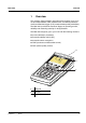
Multi 3410 Overview 1 Overview The compact, digital precision meter Multi 3410 enables you to carry out pH measurements, ORP measurements, conductivity measurements and dissolved oxygen (D.O.) measurements quickly and reliably. The Multi 3410 provides the maximum degree of operating comfort, reliability and measuring certainty for all applications.
Overview Multi 3410 The two USB interfaces (USB-A and USB-B) enable you to: z Transmit data to – a USB memory device – a PC z Update the meter firmware. 1.1 Keypad F1 F2 M CAL PRT AR STO RCL ESC MENU ENTER Multi 3410 In this operating manual, keys are indicated by brackets <..> . The key symbol (e.g.
Multi 3410 Overview : : MENU ENTER PRT _ : : Saves a measured value manually Opens the menu for the automatic save function : : Menu control, navigation Displays the manually stored measured values Displays the automatically stored measured values
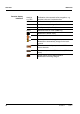
Overview Function display indicators Multi 3410 AutoCal e.g. TEC Calibration with automatic buffer recognition, e.g. with the buffer set: Technical buffers ConCal Calibration with any buffers Error An error occurred during calibration AR Stability control (AutoRead) is active HOLD Measured value is frozen ( key) Batteries are almost empty Mains operation Mains operation with charge function Batteries are automatically charged in the background.
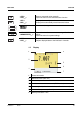
Multi 3410 Overview 1.3 Socket field 5 1 2 3 4 Connectors: 1 Digital sensors (pH, ORP, conductivity, D.O.) 2 Power pack 3 USB-A (host) interface 4 USB B (device) interface 5 Service interface CAUTION Only connect sensors to the meter that cannot return any voltages or currents that are not allowed (> SELV and > current circuit with current limiting). WTW IDS sensors and IDS adapters meet these requirements.
Overview Multi 3410 1.4 Automatic sensor recognition The automatic sensor recognition for IDS sensors allows z to operate an IDS sensor at different meters without recalibration z to operate different IDS sensors at one meter without recalibration z to assign measurement data to an IDS sensor – Measurement datasets are always stored and output with the sensor name and sensor series number.
Multi 3410 Overview Sensor data from IDS sensors IDS sensors transmit the following sensor data to the meter: z SENSOR ID – Sensor name – Sensor series number z Calibration data – Calibration date – Calibration characteristics – Calibration interval – Selected buffer set (IDS pH sensors only) – Cell constant (IDS conductivity sensors only) – Calibration history of the last 10 calibrations z Measurement settings (IDS conductivity sensors only) – The set measured parameter – The set reference temperature –
Overview 14 Multi 3410 ba75863e11 02/2011
Multi 3410 Safety 2 Safety This operating manual contains basic instructions that you must follow during the commissioning, operation and maintenance of the meter. Consequently, all responsible personnel must read this operating manual before working with the meter. The operating manual must always be available within the vicinity of the meter. Target group Safety instructions The meter was developed for work in the field and in the laboratory.
Safety Multi 3410 2.1 Authorized use The authorized use of the meter consists exclusively of the measurement of the pH, ORP, conductivity and dissolved oxygen in a field and laboratory environment. The technical specifications as given in chapter 7 TECHNICAL DATA must be observed. Only the operation and running of the meter according to the instructions given in this operating manual is authorized. Any other use is considered unauthorized. 2.
Multi 3410 Safety Safe operation If safe operation is no longer possible, the meter must be taken out of service and secured against inadvertent operation! Safe operation is no longer possible if the meter: z has been damaged in transport z has been stored under adverse conditions for a lengthy period of time z is visibly damaged z no longer operates as described in this manual. If you are in any doubt, please contact the supplier of the meter.
Safety 18 Multi 3410 ba75863e11 02/2011
Multi 3410 Commissioning 3 Commissioning 3.1 Scope of delivery z Meter Multi 3410 z 4 NiMH rechargeable batteries 1.2 V Mignon type AA z USB cable (A plug on mini B plug) z Power pack z Short instructions z Detailed operating manual (4 languages) z CD-ROM 3.2 Power supply The Multi 3410 is supplied with power in the following ways: z Battery operation with NiMh rechargeable batteries z Mains operation with the supplied power pack.
Commissioning Multi 3410 1 2 3 Place four rechargeable batteries (type Mignon AA) in the battery compartment. CAUTION Make sure that the poles of the rechargeable batteries are positioned correctly. The ± signs on the batteries must correspond to the ± signs in the battery compartment. 4 3.3.2 Close the battery compartment (2) and tighten the screws (1).
Multi 3410 Commissioning 1 Connect the plug of the power pack to the socket for the power pack on the Multi 3410. 2 Connect the original power pack to an easily accessible power outlet. During mains operation, one of the following symbols is displayed: : Mains operation with charge function Batteries are automatically charged in the background. : Mains operation Note Charge the batteries completely prior to putting the meter into operation for the first time. The charging process takes approx.
Commissioning Multi 3410 3.3.4 3 22 Setting the date and time See section 4.3.
Multi 3410 Operation Switching on 4 Operation 4.1 Switching on the meter Press the key. The meter performs a self-test. The display shows the manufacturer's logo while the self-test is being performed. If a sensor is connected, the measured value display appears. Info Switching off 22.09.2009 08:00 Press the key. 4.2 Login with a user name After activation of the user administration by the administrator, measurements are only possible after login with a user name.
Operation Multi 3410 Login User name Password Change password Admin #### 22.09.2009 08:00 2 , enter the Benutzername menu item and confirm with
Multi 3410 Operation Changing the password Forgotten the password? ba75863e11 02/2011 If the administrator has set up the access with password protection: 1 Switch on the meter with . The Login dialog box appears. 2 , enter the Benutzername menu item and confirm with
Operation Multi 3410 4.3 General operating principles This section contains basic information on the operation of the Multi 3410. Operating elements, display An overview of the operating elements and the display is given in section 1.1 and section 1.2. Operating modes, navigation An overview of the operating modes and navigation of the Multi 3410 is given in section 4.3.1 and section 4.3.2. 4.3.
Multi 3410 Operation 4.3.2 Measured value display Navigation In the measured value display, you can z open the menu for calibration and measurement settings with
Operation Multi 3410 z Functions Functions are designated by the name of the function. They are immediately carried out by confirming with
Multi 3410 Operation 4.3.3 1 Example 1 on navigation: Setting the language Press the key. The measured value display appears. The instrument is in the measuring mode. Info 2 22.09.2009 08:00 Open the Storage & config menu with
Operation Multi 3410 System General Interface Clock function Service information Reset 22.09.2009 08:00 5 Select the General submenu with . The current selection is displayed with a frame. 6 Open the General submenu with
Multi 3410 Operation 8 Select the required language with . 9 Confirm the setting with
Operation Multi 3410 Clock function Date format: Date: Time: dd.mm.yy 30.09.2009 14:53:40 22.09.2009 08:00 32 3 Select and confirm the Time menu with and
Multi 3410 Operation 4.4 Sensor-independent settings The Storage & config menu includes the following settings: z System (see section 4.4.1). z Data storage (see section 4.4.2) 4.4.
Operation Multi 3410 Menu item Setting Description System / General / Temperature unit °C °F Temperature unit, degrees Celsius or degrees Fahrenheit. All temperatures are displayed with the selected unit. System / General / Stability control on off Switches on or off the automatic stability control during measurement (see section 4.4.3) System / Interface / USB Host on off Switches on or off the USB Host interface.
Multi 3410 Operation 4.4.2 Data storage This menu contains all functions to display, edit and erase stored measured values. Note Detailed information on the storage functions of the Multi 3410 is given in section 4.10. 4.4.3 Automatic Stability control The automatic Stability control (AutoRead) function continuously checks the stability of the measurement signal. The stability has a considerable impact on the reproducibility of measured values.
Operation Multi 3410 4.5 Sensor info You can display the current sensor data and sensor settings of a connected sensor at any time. The sensor data are available in the measured value display with the [Info] softkey. Info 1 In the measured value display: Display the sensor data (sensor name, series number) with [Info]. More 2 36 22.09.2009 08:00 22.09.2009 08:00 Display further sensor data (settings) with [More].
Multi 3410 Operation SenTix 940 B092500013 Man. temperature: pH resolution mV resolution Buffer Calibration interval Unit for slope QSC: 25 °C 0.001 0.1 TEC 7d mV/pH 30.09.
Operation Multi 3410 4.6 pH value 4.6.1 General information You can measure the following parameters: z pH value [ ] z Sensor voltage [mV] Note The sensor connection and the USB-B (device) interface are galvanically isolated. This enables interference-free measurements in grounded measuring media. Temperature measurement For reproducible pH measurements, it is essential to measure the temperature of the test sample.
Multi 3410 Operation 4.6.2 Measuring the pH value 1 Perform the preparatory activities according to section 4.6.1. 2 Immerse the IDS pH sensor in the test sample. Info 3 Stability control (AutoRead ) 22.09.2009 08:00 Select the pH or mV display with . The stability control function (AutoRead) continually checks the stability of the measurement signal. The stability has a considerable impact on the reproducibility of measured values.
Operation Multi 3410 Note You can prematurely terminate the Stability control function manually with
Multi 3410 Operation 4.6.3 Overview Settings for pH measurements The following settings are possible for pH measurements: z Calibration record (display) z Calibration data storage (display) z Calibration interval z Buffers for calibration z Single-point calibration z Unit for slope z Resolution Settings The settings are made in the menu for calibration and measurement settings of the pH/ORP measurement.
Operation Multi 3410 Menu item Possible setting Description Calibration /Unit for slope mV/pH % Unit of the slope. - Starts the initial calibration with QSC buffers. QSC /First calibration The % display refers to the Nernst slope of -59.2 mV/pH (100 x determined slope/Nernst slope). This menu item is only available as long as no initial calibration was carried out with the connected IDS sensor.
Multi 3410 Operation 4.6.4 Why calibrate? When do you have to calibrate? Buffer sets for calibration ba75863e11 02/2011 pH calibration During the operation of an IDS pH sensor, the zero point (asymmetry) and slope of the sensor change with time.As a result, an inexact measured value is displayed. Calibration determines the current values of the zero point and slope of the pH sensor and stores them in the measuring instrument. Thus, you should calibrate at regular intervals.
Operation 44 Multi 3410 No. Buffer set * pH values at 8 Merck 5 * 4.010 7.000 10.000 25 °C 9 DIN 19267 1.090 4.650 6.790 9.230 25 °C 10 Mettler Toledo US * 1.679 4.003 7.002 10.013 25 °C 11 Mettler Toledo EU * 1.995 4.005 7.002 9.208 25 °C 12 Fisher 1* 2.007 4.002 7.004 10.002 25 °C 13 Fluka BS * 4.006 6.984 8.957 25 °C 14 Radiometer * 1.678 4.005 7.000 9.180 25 °C 15 Baker * 4.006 6.991 10.008 25 °C 16 Metrohm * 3.996 7.003 8.999 25 °C 17 Beckman * 4.005 7.
Multi 3410 ba75863e11 Operation 02/2011 No. Buffer set * pH values at 8 Merck 5 * 4.010 7.000 10.000 25 °C 9 DIN 19267 1.090 4.650 6.790 9.230 25 °C 10 Mettler Toledo US * 1.679 4.003 7.002 10.013 25 °C 11 Mettler Toledo EU * 1.995 4.005 7.002 9.208 25 °C 12 Fisher 1* 2.007 4.002 7.004 10.002 25 °C 13 Fluka BS * 4.006 6.984 8.957 25 °C 14 Radiometer * 1.678 4.005 7.000 9.180 25 °C 15 Baker * 4.006 6.991 10.008 25 °C 16 Metrohm * 3.996 7.003 8.
Operation Multi 3410 No. Buffer set * 20 Reagecon TEC * 2.000 4.010 7.000 10.000 25 °C 21 Reagecon 20 * 2.000 4.000 7.000 10.000 13.000 20°C 22 Reagecon 25 * 2.000 4.000 7.000 10.000 13.000 25 °C 23 Riedel-de Haen * 2.000 4.000 7.000 10.000 20°C * pH values at Brand names or trade names are trademarks of their respective owners protected by law. Note The buffers are selected in the menu, pH /
Multi 3410 Operation Calibration points Calibration can be performed using one to five buffer solutions in any order (single-point to five-point calibration). The meter determines the following values and calculates the calibration line as follows: 1-point Determined values Displayed calibration data Asy z Zero point = Asy z Slope = Nernst slope (-59.2 mV/pH at 25 °C) 2-point 3-point to 5-point Asy Slp. z Zero point = Asy Asy Slp. z Zero point = Asy z Slope = Slp. z Slope = Slp.
Operation Multi 3410 Sample record Multi 3410 Ser. no. 09250023 CALIBRATION pH Calibration date 31.07.2009 SenTix 940 Ser. no. B092500013 TEC Buffer 1 Buffer 2 Buffer 3 Voltage 1 Voltage 2 Voltage 3 Slope Asymmetry Sensor 16:13:33 4.01 7.00 10.01 184.0 mV 24.0 °C 3.0 mV 24.0 °C -177.0 mV 24.0 °C -60.2 mV/pH 4.0 mV +++ etc... Calibration evaluation After calibrating, the meter automatically evaluates the calibration. The zero point and slope are evaluated separately.
Multi 3410 Operation Preparatory activities Perform the following preparatory activities when you want to calibrate: 1 Connect the IDS pH sensor to the meter. The pH measuring window is displayed. 2 Keep the buffer solutions ready. 4.6.5 Calibration interval The calibration evaluation is displayed as a sensor symbol. After the QSC function has been enabled the sensor symbol is replaced by the QSC color scale (see section 4.6.10).
Operation Multi 3410 4.6.6 Carrying out an automatic calibration (AutoCal) Make sure that in the sensor menu, Buffer menu, the buffer set is correctly selected (see section 4.6.3). Use any one to five buffer solutions of the selected buffer set in ascending or descending order. Below, calibration with Technical buffers (TEC) is described. When other buffer sets are used, other nominal buffer values are displayed. Apart from that, the procedure is identical.
Multi 3410 Operation 22.09.2009 08:00 7 Wait for the end of the measurement with stability control or accept the calibration value with
Operation Continuing with twopoint calibration Multi 3410 9 Thoroughly rinse the IDS pH sensor with deionized water. 10 Immerse the IDS pH sensor in buffer solution 2. 11 When measuring without temperature sensor: Measure the temperature of the buffer manually and enter it with . 12 Start the measurement with
Multi 3410 Operation Continuing with threeto five-point calibration 15 Thoroughly rinse the IDS pH sensor with deionized water. 16 Immerse the IDS pH sensor in the next buffer solution. 17 When measuring without temperature sensor: Measure the temperature of the buffer manually and enter it with . 18 Start the measurement with
Operation Multi 3410 4.6.7 Carrying out a manual calibration (ConCal) Make sure that in the sensor menu, Buffer menu, the ConCal buffer set is correctly selected (see section 4.6.3). Use any one to five buffer solutions in ascending or descending order. Note If single-point calibration was set in the menu, the calibration procedure is automatically finished with the measurement of buffer solution 1 and the calibration record is displayed.
Multi 3410 Operation 22.09.2009 08:00 7 Wait for the measurement with stability control to be completed or terminate the stability control and take over the calibration value with
Operation Continuing with twopoint calibration Multi 3410 11 Thoroughly rinse the IDS sensor with deionized water. 12 Immerse the IDS pH sensor in buffer solution 2. 13 When measuring without temperature sensor: Measure the temperature of the buffer manually and enter it with . 14 Start the measurement with
Multi 3410 Operation Continuing with threeto five-point calibration 19 Thoroughly rinse the IDS pH sensor with deionized water. 20 Immerse the IDS pH sensor in the next buffer solution. 21 When measuring without temperature sensor: Measure the temperature of the buffer manually and enter it with . 22 Start the measurement with
Operation Multi 3410 4.6.8 Displaying calibration records The calibration data can be displayed and then output to the interface. Displaying the calibration record The calibration record of the last calibration is to be found under the menu item, Calibration / Calibration record. To open it in the measured value display, press the key. _ The calibration records of the last 10 calibrations are to be found in the menu, Calibration / Calibration data storage / Display.
Multi 3410 Operation 4.6.9 Continuous measurement control (CMC function) The Continuous Measurement Control (CMC function) facilitates to evaluate the current measured value instantly and definitely. After each successful calibration the scale of the pH measuring range is displayed in the measured value display. Here you can very clearly see whether or not the current measured value is in the calibrated part of the measuring range. The following information is displayed: 1 2 3 4 Info 22.09.
Operation Multi 3410 4.6.10 QSC function (sensor quality control) General information on the QSC function The QSC function (Quality Sensor Control) is a new sensor evaluation for digital IDS sensors. It evaluates the condition of an IDS pH sensor individually and with a very fine grading. On the display, the QSC color scale (from green to yellow) indicates the current sensor evaluation by means of a pointer. QSC color scale Info 22.09.
Multi 3410 Operation QSC calibration The QSC function is enabled by once carrying out an additional threepoint calibration with special QSC buffer solutions. It covers the measuring range of the sensor from pH 2 to pH 11. The QSC initial calibration determines the actual condition of the sensor and stores it as a reference in the sensor. To meet the high requirements of a QSC initial calibration, the QSC initial calibration should optimally be carried out with the initial commissioning of the sensor.
Operation Multi 3410 4 As soon as the three-point calibration has been successfully carried out you can decide whether to accept or discard the calibration as the QSC initial calibration. The QSC initial calibration is completed. The sensor is calibrated. If you want to calibrate with special buffers for your measurements, you can subsequently carry out a normal calibration with your buffers.
Multi 3410 Operation 4.7 ORP voltage 4.7.1 General information You can measure the following parameters: z ORP [mV] Note The sensor connection and the USB-B (device) interface are galvanically isolated. This enables interference-free measurements in grounded measuring media. Preparatory activities Perform the following preparatory activities when you want to measure: 1 Connect the IDS ORP sensor to the meter. The ORP measuring window is displayed. 2 Check the meter with the IDS ORP sensor. 4.7.
Operation Stability control (AutoRead ) Multi 3410 The stability control function (AutoRead) continually checks the stability of the measurement signal. The stability has a considerable impact on the reproducibility of measured values. The display of the measured parameter flashes until a stable measured value is available. You can start the Stability control manually at any time, irrespective of the setting for automatic Stability control (see section 4.4.3) in the System menu.
Multi 3410 Operation 4.7.3 Overview Settings for ORP measurements The following settings are possible for ORP measurements: z Resolution z Automatic stability control Settings ba75863e11 02/2011 The settings are made in the menu for measuring settings of the ORP measurement. To open the settings, display the required parameter in the measured value display and press the
Operation Multi 3410 4.8 Dissolved oxygen 4.8.1 General information You can measure the following parameters: z D.O. concentration z D.O. saturation index ("D.O. saturation") z D.O. partial pressure Note The sensor connection and the USB-B (device) interface are galvanically isolated. This enables interference-free measurements in grounded measuring media. Temperature measurement IDS D.O. sensors measure the temperature with a temperature sensor integrated in the IDS sensor.
Multi 3410 Operation 4.8.2 Measuring 1 Perform the preparatory activities according to section 4.9.1. 2 Immerse the D.O. sensor in the test sample. Info Selecting the displayed measured parameter 22.09.2009 08:00 You can switch between the following displays with : z D.O. concentration [mg/l] z D.O. saturation [%] z D.O. partial pressure [mbar]. Salinity correction When measuring the concentration of solutions with a salt content of more than 1 g/l, a salinity correction is required.
Operation Multi 3410 2 Stability control (AutoRead ) Release the frozen measured value again with . The HOLD function is switched off. The [HOLD] status display disappears. The stability control function (AutoRead) continually checks the stability of the measurement signal. The stability has a considerable impact on the reproducibility of measured values. The display of the measured parameter flashes until a stable measured value is available.
Multi 3410 Operation Criteria for a stable measured value The Stability control function checks whether the measured values are stable within the monitored time interval. Measured parameter Time interval Stability in the time interval D.O. concentration 20 seconds Δ : better than 0.03 mg/l D.O. saturation 20 seconds Δ : better than 0.4 % D.O. partial pressure 20 seconds Δ : Better than 0.8 mbar The minimum duration until a measured value is assessed as stable is the monitored time interval.
Operation Multi 3410 4.8.3 Overview Settings for D.O. sensors (menu or measurement and calibration settings) The following settings are possible for D.O. sensors: z Calibration record (display) z Calibration data storage (display) z Calibration interval z FDO Check z Check interval z Salinity correction z Salinity (salinity equivalent) Settings The settings are available in the menu for measurement and calibration settings.
Multi 3410 Operation Menu item Possible setting Description FDO Check / Check interval 1 ... 60 ... 999 d Interval for the FDO Check (in days). Sal correction on off Manual salt content correction for concentration measurements Salinity 0.0 ... 70.0 Salinity or salinity equivalent for the salt content correction. The FDO Check status display indicator in the measuring window reminds you to check the sensor regularly.
Operation Multi 3410 4.8.4 Why should you check the sensor? When should you check the sensor? FDO® Check procedure (check of the FDO® 925) With the FDO® Check procedure, you can find out in a simple manner whether the FDO® 925 D.O. sensor should be cleaned or calibrated.
Multi 3410 Operation 22.03.2010 08:00 Evaluation 4 Start the measurement with
Operation Multi 3410 4.8.5 Why calibrate? D.O. calibration D.O. sensors age. This changes the slope of the D.O. sensor. Calibration determines the current slope of the sensor and stores this value in the instrument. Note The FDO® 925 D.O. sensor ages so little it does not have to be regularly calibrated. To detect changes of the sensor as early as possible, the FDO® Check procedure can be useful (see section 4.8.4).
Multi 3410 Operation Calibration evaluation of the FDO® 925 Display Error Calibration record Relative slope +++ S = 0.94 ... 1.06 ++ S = 0.92 ... 0.94 or S = 1.06 ... 1.08 + S = 0.90 ... 0.92 or S = 1.08 ... 1.10 Error S < 0.90 or S > 1.10 Eliminate the error according to chapter 6 WHAT TO DO IF... Calibration in water vaporsaturated air Proceed as follows to calibrate the D.O. sensor: 1 Connect the D.O. sensor to the meter. 2 Place the FDO® 925 D.O.
Operation Multi 3410 22.03.2010 08:00 76 4 Start the measurement with
Multi 3410 Operation 4.8.6 Displaying calibration records The calibration data can be displayed and then output to the interface. Displaying the calibration record The calibration record of the last calibration is available under the menu item, Calibration / Calibration record. To open it in the measured value display, press the key. _ The calibration records of the last 10 calibrations are available in the menu, Calibration / Calibration data storage / Display.
Operation Multi 3410 4.9 Conductivity 4.9.1 General information You can measure the following parameters: z Conductivity z Specific resistance z Salinity z Total dissolved solids (TDS) Note The sensor connection and the USB-B (device) interface are galvanically isolated. This enables interference-free measurements in grounded measuring media. Temperature measurement IDS sensors measure the temperature with a temperature sensor integrated in the IDS sensor.
Multi 3410 Operation Selecting the displayed measured parameter You can switch between the following displays with : z Conductivity [μS/cm] / [mS/cm] z Resistivity [Ω·cm] / [kΩ·cm] / [MΩ·cm] z Salinity SaL [ ] z Total dissolved solids TDS [mg/l] / [g/l] The factor to calculate the total dissolved solids is set to 1.00 in the factory. You can adjust this factor to meet your requirements in the range of 0.40 to 1.00. The factor is set in the menu for the parameter, TDS.
Operation Multi 3410 2 Using
Multi 3410 Operation 4.9.3 Temperature compensation The calculation of the temperature compensation is based on the preset reference temperature, 20 °C or 25 °C. It appears on the display as Tr20 or Tr25. You can select one of the following temperature compensation methods: z Nonlinear temperature compensation (nLF) according to EN 27 888 z Linear temperature compensation (lin) with adjustable coefficients of 0.000 ... 3.
Operation Multi 3410 4.9.4 Overview Settings for IDS conductivity sensors The following settings are possible for IDS conductivity sensors: z Calibration record (display) z Calibration data storage (display) z Calibration interval z Reference temperature z Temperature compensation z TDS factor z Unit of the temperature Settings Setting menu of TetraCon 925 The settings are made in the menu for the measured parameter, conductivity.
Multi 3410 Operation Menu item Possible setting Type Description Measuring cell used Cal Measuring cells whose cell constant is determined by calibration in the KCL control standard solution. Calibration range: 0.450 to 0.500 cm-1 The currently valid cell constant is displayed in the status line. man Freely adjustable cell constant in the range 0.450 ... 0.500 cm-1. Man. cell const. 0.450 ... 0.475 ... 0.500 cm-1 The cell constant and be displayed and set here Temp. comp.
Operation Setting menu of LR325/01 Multi 3410 Menu item Possible setting Description Cell constant 0.090 ... ... 0.100 ... 0.110 cm-1 The cell constant can be displayed and set here Temp. comp. (TC) / Method nLF lin off Procedure for temperature compensation (see section 4.9.3). This setting is only available for the measured parameters, ϰ and ρ. Temp. comp. (TC) / Linear coeff. 0.000 ... 2.000 ... 3.000 %/K Coefficient of the linear temperature compensation.
Multi 3410 Operation 4.9.5 Determining the cell constant (calibration in control standard) Why determine the cell constant? Aging slightly changes the cell constant, e. g. due to coatings. As a result, an inexact measured value is displayed. The original characteristics of the cell can often be restored by cleaning the cell. Calibration determines the current value of the cell constant and stores this value in the meter. Thus, you should calibrate at regular intervals (we recommend: every 6 months).
Operation Multi 3410 Display Calibration record Error Error Cell constant [cm-1] Outside the range 0.450 ... 0.500 cm-1 Eliminate the error according to chapter 6 WHAT TO DO IF... Determining the cell constant For this calibration procedure, the Type setting must be set to cal . Proceed as follows to determine the cell constant: 1 Connect an IDS conductivity sensor to the meter. 2 In the measured value display, select the conductivity parameter with . 3 Start the calibration with .
Multi 3410 Operation 4.9.6 Displaying calibration records The calibration data can be displayed and then output to the interface. Displaying the calibration record The calibration record of the last calibration is to be found under the menu item, Calibration / Calibration record. To open it in the measured value display, press the key. _ The calibration records of the last 10 calibrations are to be found in the menu, Calibration / Calibration data storage / Display.
Operation Multi 3410 4.10 Data storage You can transmit measured values (datasets) to the data storage: z Manual storage (see section 4.10.1) z Automatic storage at intervals (see section 4.10.2) Each storage process transmits the current dataset to the interface at the same time.
Multi 3410 Operation 4.10.1 Manual storage You can transmit a measurement dataset to the data storage as follows. The dataset is at the same time output to the interface: 1 Press the key shortly. The menu for manual storage appears. Manual data storage 4 From 500 30.09.2009 11:24:16 pH 7.000 24.8 °C AR +++ ID number: Continue 1 22.09.2009 08:00 2 If the storage is full If necessary, change and confirm the ID number (1 ... 10000) with and
Operation Multi 3410 Automatic data storage ID number Interval Duration Continue 1 30 s 180 min Max. available storing duration 0d03h00min 0 Set entire storing duration 1d17h33min 22.09.2009 08:00 Graphical display of the storage usage Settings You can configure the automatic storage function with the following settings: Menu item Possible setting Description ID number 1 ...
Multi 3410 Operation Remaining storing duration Graphical display of the storing duration 0d03h00min 30.09.2009 08:00 The active automatic storage function can be recognized by the progress bar in the status line. The progress bar indicates the remaining storing duration. Note If the automatic storage function is activated, only the following keys are active: , and . The other keys and the automatic switch-off function are deactivated.
Operation Multi 3410 4.10.3 Editing the measurement data storage The contents of the manual or automatic measurement data storage can be shown on the display. Each of the measurement data storages has a function to erase the entire contents. Editing the data storage The storage is edited in the menu, Storage & config / Data storage. To open the Storage & config menu, press the
Multi 3410 Operation Display presentation of a dataset Manual data storage (500) 3 of 64 30.09.2009 11:24:16 ID number: 1 SenTix 940 B20234008565 pH 7.000 24.8 °C AR Sensor: +++ 22.09.2009 08:00 Sample printout 31.07.2009 09:56:20 Multi 3410 Ser. no. 09250023 SenTix 940 Ser. no. B092500013 ID number 2 pH 6.012 24.8 °C, AR, Sensor: +++ ________________________________________ 31.07.2009 10:56:20 Multi 3410 Ser. no. 09250013 SenTix 940 Ser. no. B092500013 ID number 2 pH 6.012 24.
Operation Multi 3410 4.11 Transmitting data (USB interfaces) 4.11.1 Outputting current measurement data 1 Output the current measurement data to the USB-B interface with . 4.11.2 Transmitting data (to a PC) The meter has the following interfaces: z USB-B interface (USB Device) e.g. to connect a PC z USB-A interface (USB Host), e.g. to connect a USB flash drive Via the USB-B interface (USB Device) you can transmit data to a PC or printer and update the meter software.
Multi 3410 Operation 4 Set the same transmission data at the connected instrument (PC): z Baud rate: to be selected in the range 1200 ... 19200 z Handshake: RTS/CTS z Set at the PC only: – Parity: none – Data bits: 8 – Stop bits: 1 4.11.4 Options for data transmission to a PC (USB-B interface) Via the USB-B interface you can transmit data to a PC.
Operation Multi 3410 4.11.5 Connecting the USB memory device / USB-A interface (USB Host) Connect the USB-A interface (USB Host) of the Multi 3410 to a USB flash drive. 1 Connect a USB flash drive to the USB Host interface. 4.11.6 Data transmission to a USB memory device (USB-A interface) Via the USB-A interface you can transmit data to a USB memory device.
Multi 3410 Operation 4.12 Reset You can reset (initialize) all sensor settings and sensor-independent settings separately from each other. 4.12.1 Resetting the measurement settings Note The calibration data are reset to the default settings together with the measuring parameters. Recalibrate after performing a reset. pH The following settings for pH measurements are reset to the default settings with the Reset function: Setting Default settings Buffer AutoCalTEC Cal.
Operation Multi 3410 the required parameter in the measured value display and press the
Multi 3410 Operation 4.12.2 Resetting the system settings The following system settings can be reset to the default condition: Setting Default settings Language English Acoustic signal On Volume 6 Baud rate 4800 Baud Output format ASCII Decimal separator . Brightness 15 Illumination Auto Switchoff time 1h Temperature unit °C USB Host On Stability control On The system settings are reset in the menu, Storage & config / System / Reset.
Operation 100 Multi 3410 ba75863e11 02/2011
Multi 3410 Maintenance, cleaning, disposal 5 Maintenance, cleaning, disposal 5.1 Maintenance The only maintenance activity required is replacing the batteries. Note See the relevant operating manuals of the IDS sensors for instructions on maintenance. 5.1.1 Replacing the rechargeable batteries 1 Unscrew the two screws (1) on the underside of the meter. 2 Open the battery compartment (2) on the underside of the meter. 1 2 3 Remove the four rechargeable batteries from the battery compartment.
Maintenance, cleaning, disposal Multi 3410 5 5.2 Close the battery compartment (2) and tighten the screws (1). Cleaning Occasionally wipe the outside of the measuring instrument with a damp, lint-free cloth. Disinfect the housing with isopropanol as required. CAUTION The housing is made of synthetic material (ABS). Thus, avoid contact with acetone or similar detergents that contain solvents. Remove any splashes immediately. 5.3 Packing This meter is sent out in a protective transport packing.
Multi 3410 What to do if... Sensor symbol flashes 6 What to do if... 6.1 General information Cause Remedy – Calibration interval expired – Recalibrate the measuring system Cause Remedy – Batteries almost empty – Charge the batteries (see section 3.3.2 CONNECTING THE POWER PACK / CHARGING THE BATTERIES) Display – Replace the batteries (see section 5.
What to do if... Data transmission to USB memory device does not work Multi 3410 Cause Remedy – Connected USB memory device has not been recognized, e. g. – Use other USB memory device – the USB memory device has been formattet to a file system which is not supported (e. g. NTFS) Error message, Only use rechargeable batteries! Ni-MH 1.2 V, >2100 mAh – Reformat the USB memory device to FAT 16 or FAT 32 file system (Caution: Reformatting erases all data on the USB memory device.
Multi 3410 What to do if... 6.
What to do if...
Multi 3410 What to do if... Error message, Error Cause Remedy – Sensor contaminated – Clean the sensor – Measured temperature outside the operating conditions (OFL/UFL displayed instead of temperature value) – Observe the temperature range for the measuring medium – Defective sensor – Replace sensor Note More information, as well as notes on cleaning and replacement of sensors, are given in the documentation of your sensor. 6.
What to do if...
Multi 3410 Technical data Dimensions Weight Mechanical structure 7 Technical data 7.1 General data Approx. 180 x 80 x 55 mm Approx. 0.4 kg Type of protection IP 67 Electrical safety Protective class III Test certificates CE Ambient conditions Power supply USB interface (device) USB interface (host) Storage - 25 °C ... + 65 °C Operation -10 °C ... + 55 °C Allowable relative humidity Annual mean: < 75 % 30 days/year: 95 % Other days: 85 % Rechargeable batteries 4 x 1.
Technical data Applicable directives and standards Multi 3410 EMC EC directive 2004/108/EC EN 61326-1 EN 61000-3-2 EN 61000-3-3 FCC Class A Meter safety EC directive 2006/95/EC EN 61010-1 IP protection class EN 60529 7.2 Measuring ranges, resolution, accuracy Note These data are given in the documentation of your sensor. FCC Class A Equipment Statement Note: This equipment has been tested and found to comply with the limits for a Class A digital device, pursuant to Part 15 of the FCC Rules.
Multi 3410 Lists 8 Lists This chapter provides additional information and orientation aids. Specialist terms Index The glossary briefly explains the meaning of the specialist terms. However, terms that should already be familiar to the target group are not described here. The index will help you to find the topics that you are looking for. Glossary Adjusting To manipulate a measuring system so that the relevant value (e. g.
Lists Multi 3410 ORP voltage Oxygen saturation Short name for "Relative D.O. saturation". pH value The pH value is a measure of the acidic or basic effect of an aqueous solution. It corresponds to the negative decadic logarithm of the molal hydrogen ions activity divided by the unit of the molality. The practical pH value is the value of a pH measurement. Potentiometry Name of a measuring technique. The signal (depending on the measured parameter) of the electrode is the electrical potential.
Multi 3410 Index A Air calibration beaker . . . . . . . . . . . . . . . . . 68 Authorized use . . . . . . . . . . . . . . . . . . . . . . 18 Automatic switch-off . . . . . . . . . . . . . . . . . . 25 AutoRead Conductivity . . . . . . . . . . . . . . . . . . . . . 73 O2 . . . . . . . . . . . . . . . . . . . . . . . . . . . . 65 ORP . . . . . . . . . . . . . . . . . . . . . . . . . . . 61 pH . . . . . . . . . . . . . . . . . . . . . . . . . . . . 38 F B K Firmware update . . . . . . . . . . . . . . . .
Index Multi 3410 Scope of delivery . . . . . . . . . . . . . . . . . . . . 21 Setting the date . . . . . . . . . . . . . . . . . . . . . 23 Setting the time . . . . . . . . . . . . . . . . . . . . . 23 Single-point calibration pH . . . . . . . . . . . . . . . . . . . . . . 49, 52, 53 Slope pH . . . . . . . . . . . . . . . . . . . . . . . . . . . . 42 Slope, relative . . . . . . . . . . . . . . . . . . . . . . 68 Socket field . . . . . . . . . . . . . . . . . . . . . . . . 13 Stability control automatic .
Multi 3410 Appendix: Firmware update 9 Appendix: Firmware update With the Multi 3410 you can update the firmware of your meter and IDS sensors. 9.1 General information Firmware update for the meter Multi 3410 Available firmware updates for the meter are provided on the Internet. With the "Firmware Update " program and a PC you can update the firmware of the Multi 3410 to the newest version. For the update you have to connect the meter to a PC.
Appendix: Firmware update Multi 3410 9.2 General information Firmware-Update for IDS Sensors Available firmware updates for IDS sensors are provided on the Internet. With the "Firmware Update" program and a PC you can update the firmware of an IDS sensor to the newest version. For updating, connect the IDS sensor to the Multi 3410, and the Multi 3410 to a PC.
Wissenschaftlich-Technische Werkstätten GmbH Dr.-Karl-Slevogt-Straße 1 D-82362 Weilheim Germany Tel: Fax: E-Mail: Internet: +49 (0) 881 183-0 +49 (0) 881 183-100 +49 (0) 881 183-420 Info@WTW.com http://www.WTW.