Global Water Instrumentation SIT65 Users Manual Internet Accessible Satellite Telemetry Solutions Global Water Instrumentation, Inc. 151 Graham Road P.O. Box 9010 College Station, TX 77842-9010 Telephone : 800-876-1172 International : (979) 690-5560, Fax : (979) 690-0440 e-mail : globalw@globalw.
Global Water Instrumentation Introduction ...................................................................... 3 Controller Layout ............................................................. 4 Analog Inputs .................................................................... 5 Digital Inputs .................................................................... 6 Digital Control Outputs ................................................... 7 Time Stamps and Latency Time ....................................
Global Water Instrumentation Introduction Thank you for the purchase of a Global Water SIT65 Satellite Telemetry Station. This instrument has been quality tested to provide you with accurate and reliable operation for your remote monitoring needs. We are confident that you will find this product to be a valuable asset to your applications. Should you require any assistance, our technical staff will be happy to help.
Global Water Instrumentation are rarely more than the cost of recovering data from even slightly remote locations, but they should be considered. For more information on applications and subscription fees, please consult Global Water. Each station is identified by a unique Radio Name and Station ID# which are used by the satellites for communicating with the field station. These numbers can be found on the documentation provided with the system, or on labels placed on the radio modem and controller board.
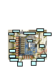
Global Water Instrumentation Analog Inputs There are provisions for up to 8 analog inputs. The number of enabled inputs is factory programmable but the inputs can be configured by the user as 0-20mA, 01mA, 0-500uA, 0-5VDC or 0-10VDC. To conserve power, the sensors connected to these inputs are usually switched on only when readings are being taken, the sensor warm-up time.
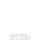
Global Water Instrumentation The jumper settings for the analog input configurations are as follows: Input Type 0-20mA 0-1mA 0-500uA 0-10VDC 0-5VDC Jumper 1 2a-2b 1a-2a 1a-2a 1a-2a 1a-2a Jumper 2 3a-4a 3a-3b 4a-4b 4b-5b 3a-4a Sensor Power 18V Switched 12V Switched 5V Switched 12V Continuous Jumper 3 7a-8a 7a-7b 6a-7a 7a-8a Jumper 4 9a-9b 9a-9b 9a-9b 8b-9b Digital Inputs Up to 3 digital inputs are available that can be configured in any combination of accumulators (rain gauges, flow sensors) or status
Global Water Instrumentation Digital Control Outputs There are up to two control outputs available that can be used to remotely control pumps, valves, lights, etc. These are open-collector outputs that source current to ground with a maximum of 100mA per channel. Driving larger loads requires a relay or some other type of switching device. The outputs are protected from driving inductive loads. Enabling the use of these output channels is a factory programmable option only.
Global Water Instrumentation Time Stamps and Latency Time Latency time is the total time between the SIT65 transmitting data and the data appearing on the hosting web site. The data is held in the radio module until one of the satellites is within range, and then sent. The information is further held at the satellite until its data buffers are full before relaying it to one of several ground stations where it is transferred to the Internet.
Global Water Instrumentation Real-Time Time Stamp In cases where the time stamp is more critical, a real-time time stamp feature can be enabled. This is a factory programmable feature that allows the field station to transmit the actual time the data readings were taken along with the sensor data. Because the time stamp is transmitted through the satellite network, the amount of data being sent increases, along with the subscription fees charged by Orbcomm.
Global Water Instrumentation hours. Systems that require access to interrogation and control should have power systems designed according to the requirements of the system. The voltage thresholds for the different power modes are as follows: Battery Voltage >= 12.8 volts; Battery Charging. The battery has sufficient charge and the radio remains on all of the time to receive commands. 12.0 volts < Battery Voltage < 12.8 volts; Low battery. Radio remains on only when data is being transmitted. 11.
Global Water Instrumentation Typically, a system is designed to make sufficient power available during the worst times of the year. In these cases, solar panels should be oriented to gather the most light when the sun is lowest in the sky. In areas with snow, they may even be pointed lower to allow the snow to slide off. This reduces the efficiency but overall, will probably produce more total current.
Global Water Instrumentation Station ID and Sensor Offsets Each field station has a unique Station ID number. This number is shown on the configuration report provided with the system, and on a label placed at the top of the controller board. The databases identify the sensor data for each of the input channels using this station ID along with a sensor offset number. The offset is added to the station ID to calculate the unique sensor number.
Global Water Instrumentation Sensor Data Format Analog sensor data is transmitted as a 10-bit number in the range of 0-1023. A calibration equation is applied to the raw data number at the database to scale the sensor reading in the appropriate range and engineering units. Digital input accumulators count input events from things like tipping bucket rain gauges and flow monitors. The accumulator is transmitted as a 11-bit number in the range of 0-2047 and calibration factors are also used to scale the data.
Global Water Instrumentation converting water level to flow, or can be used as best-fit polynomial approximations for almost any non-linear sensor or function. These features are available in both databases, but they work differently and the format won’t be detailed here. Alarms Alarm notifications can be sent via email or text messaging when incoming data exceeds thresholds defined in the alarms section of the databases.
Global Water Instrumentation installed so that there is nothing alongside of it all the way down to its base for at least 4-6 feet in all directions, the further the better. This includes the mast it is mounted on, solar panels, walls, towers, etc. Locations near sources of electrical noise may also limit the performance, especially radio frequencies in the VHF band. The antenna is provided with 16 feet of cable.
Global Water Instrumentation Troubleshooting The biggest source of trouble is due to insufficient battery voltage. If the unit is transmitting erratically or has stopped, look at the trend in battery voltage going back a week or more. The battery voltage monitor can be a very good indicator of what the problem may be. Sudden changes in system voltage may be caused by sudden changes in the local environmental, an electrical problem that is drawing excessive current, or a problem with the charging system.
Global Water Instrumentation and also has sufficient signal strength. It blinks orange once each second when the received signal is too weak to communicate. Buffer: Data Buffer. This yellow LED is lit when there is data in the data buffer waiting to be transmitted, and off when the data buffer is empty. Some typical problems indicated by the operation of these LED’s are: • The SV LED blinks every 5 seconds and the modem LED’s are off. The battery voltage is too low and the modem has been turned off.
Global Water Instrumentation Technical Support: Call Global Water for technical support or sales information: Phone: (800) 876-1172 (979) 690-5560 Fax: (979) 690-0440 Email: globalw@globalw.com.
Global Water Instrumentation Appendix A: Specifications Analog Inputs: Up to 8 inputs available 10-bit resolution Type: 0-20mA, 0-1mA, 0-500uA, 0-5VDC, 0-10VDC Sensor Power: 5Vsw, 12Vsw, 18Vsw or 12V Continuous Digital Inputs: Up to 3 inputs available, counters or status Contact closure or open collector to ground Inputs have 20K pull-up resistor to 5VDC Maximum accumulator count: 2047 (11-bit) Control Outputs: Up to 2 outputs available Open collector output to ground 100mA each output maximum Induct
Global Water Instrumentation Appendix B: Adder and Multiplier Numbers 1) Define the Engineering Units (EU) and span (0 to 100 MPH, -50°C to +50°C, etc). EU(min) = Minimum EU corresponding to minimum sensor output EU(max) = Maximum EU corresponding to maximum sensor output EU(span) = EU(max) – EU(min), observe polarity 2) Calculate the Raw Data (RD) span.