
User Manual


Global Water Instrumentation
5
Analog Inputs
There are provisions for up to 8 analog inputs. The number of enabled inputs is
factor y pr ogr am m able but the inputs c an be c onfigured by the user as 0-20mA, 0-
1mA, 0-500uA, 0-5VDC or 0-10VDC. To conserve power, t he s ens or s connect ed to
these inputs ar e us ually switched on only when readings ar e being taken, the sensor
warm-up time. This warm-up t im e is a factory programmed setting but the voltage
powering the sens or s dur ing this time is user configurable for 5V, 12V or 18V
switched; or 12 volts continuous. The sensor warm-up time s ett ing applies to all
analog channels. Setting the configuration jumpers for 12 volt continuous operation
defeats the sensor power switch and war m -up tim e and power s the sensor
connected t o that analog channel at 12 v olts all the time.
The quick-connec t input connector s ar e c olor c oded for eas y w iring. The ground
terminals ar e black , sensor power is red, and t he sensor input is white. Insert the
wire into the c onnec tor and push the locking lev er dow n. To release the wire, lift the
lever up until it loc k s it place.
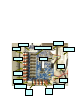
Each channel can be configured separately us ing jumpers on the c ontroller board.
Two jumpers ar e us ed for the input type and two are used to select the sensor
voltage. The jumper settings are the same for each channel. The diagr am below
illustrat es a 0-20mA (4-20mA) input with 12V DC swit c hed s ens or pow er . Disconnect
the batt er y when c onnec ting sensors or c hanging the jumper sett ings .