
User Manual


Global Water Instrumentation
6
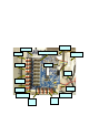
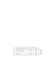
The jumper settings for the analog input configurations are as follows:
Input T y pe Jumper 1 Jumper 2
0-20mA 2a-2b 3a-4a
0-1mA 1a-2a 3a-3b
0-500uA 1a-2a 4a-4b
0-10VDC 1a-2a 4b-5b
0-5VDC 1a-2a 3a-4a
Sensor Power Jumper 3 Jumper 4
18V Switched 7a-8a 9a-9b
12V Switched 7a-7b 9a-9b
5V Switched 6a-7a 9a-9b
12V Continuous 7a-8a 8b-9b
Digital Inputs
Up to 3 digital input s ar e av ailable that can be configured in any combination of
accumulator s ( r ain gauges, flow sensors ) or status inputs (doors sw itches, power
failure). These inputs can also be progr am med to init iate a transmis s ion on any
change of st ate (event), a door opening or a pu m p turning on for ex ample. A l l input
configurat ions ar e factory programmable only.
The quick-connec t input connector s ar e c olor c oded for eas y w ir ing. Black terminals
are connected to ground, red ter m inals ar e c onnected to 12VDC continuously , and
the digital input s ar e c olor ed white. Insert t he wire int o the connector and push the
locking lever down. To release the wire, lif t the lever up until it lock s it place.
The digital inputs have 20Kohm pull-up resis tors to the +5volt internal power supply
of the cir c uit board. This input is intended t o be s witched to ground only, either by a
switch contact closure or by a s w itching transistor. Driv ing these inputs with a
positive voltage other than 5volts can result in excess c ur r ent drain and improper
circuit oper ation.