Global Water OWNER’S MANUAL TB500 Series Turbidimeter Catalog No. 24034GW (2/07) Rev. 1.1 Global Water Instrumentation 11390 Amalgam Way Gold River, CA 95670 Phone: 800-876-1172 Fax: 916-638-3429 E-Mail: globalw@globalw.com Website: www.globalw.
TB500 (2/07) Rev. 1.
Table of Contents Section Page Specifications.....................................................................................................1 1.0 Overview............................................................................................................2 1.1 The TB500 Series .................................................................................2 1.2 Unpacking and Inspection of the Instrument and Accessories .............3 1.3 The Display .........................................
Table of Contents (continued) Section Page 7.6 7.7 7.8 7.9 7.10 7.11 7.12 7.13 7.14 7.15 Enabling the Security Access...............................................................20 Extended Settings.................................................................................20 Speed of Response ...............................................................................20 Displayed Resolution ..........................................................................21 LCD Backlight Brightness....
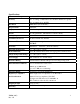
Specifications Measurement Range 0 – 1000.0 NTU Accuracy ±2% of reading or ±0.02 NTU below 40 NTU whichever is greater ±5% of reading above 40 NTU Resolution 0.0001 NTU (below 10 NTU) Response Time Adjustable Display Multi-Line Liquid Crystal Backlit Display Alarms Two Programmable, 120-240VAC 2A Form C Relay Analog Output Powered 4-20 mA, 600 Ω drive Communications Port Bi-directional RS-485, Modbus Maximum Water Pressure Integral pressure regulator rated 1380kPa (200 PSI.
1.0 Overview The TB500 process turbidimeter allows for the measurement of the turbidity of process water on-line. The White Light TB500 has been designed to meet the design criteria specified by the US EPA 180.1 on turbidity measurement. The infrared TB500 was designed to meet the design criteria specified in ISO 7027 and DIN 27027 for the measurement of the turbidity of a sample. Both models have long life lamps. Some models have ultrasonic cleaning. Refer to section 8.2 for more information. 1.
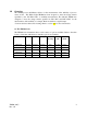
1.2 Unpacking and Inspection of the Instrument and Accessories The table below indicates the items in the turbidimeter shipment. Item TB500 Turbidimeter c/w Field Terminal Box & Flow Through Assembly Quantity Instruction Manual 1 Desiccant Pack 1 Cuvette (Single Pack) 1 Tubing Kit: 1-shutoff clamp 1-backpressure valve 2-connecting tubing with fittings for flow through assembly 1-drain vent screw (used in pressurized systems) 1 1 Remove the instrument from the packing carton.
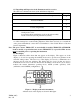
1.4 The Touch Pad Figure 2 illustrates the touch pad. The touch pad has four buttons: MODE/EXIT, ↵, t, and u. The MODE/EXIT button is used to cycle between the three operational modes of the instrument: CAL, CONFIG, and AUTO (Measurement) mode. The ↵ button enters the option (or mode that is highlighted or chosen. The tand u buttons are used to change settings. Figure 2: Touch Pad 1.5 Vapor Purge The TB500 is equipped with a continuous vapor purge system.
3.0 Installation and Commissioning Prior to use for the first time, the supplied desiccant pouch will need to be installed. Refer to section 10.2 Replacing or Installing the Desiccant Pouch. 3.1 Mounting & Site Selection The instrument is designed for wall mounting. If wall mounting is not practical, the instrument can be mounted on any suitable level surface.
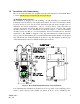
3.2 Plumbing The recommended plumbing for the instrument is shown in Figure 4. The instrument is designed to require very little head pressure to operate; around 6.9kPa (1 PSI). The flow through cuvette is rated for a flow of 100ml/min. – 1 liter/min. (0.026-0.26Gal/min). The integral pressure regulator is rated for a maximum pressure of 1380 kPa (200 PSI.). The maximum allowable fluid temperature is 50°C (122°F).
3.2.1 Drain Vent: The TB500 has been fitted with a drain vent in the “OUT” bulkhead fitting. This fitting allows for atmospheric equalization, thus helping to alleviate bubble formation in the cuvette. Refer to Figure 4. Upon initial flow minor leakage may occur through the drain vent. This will subside once normal flow is established. For some high pressure systems, where the vent hole continuously leaks, a 6:32 seal screw is provided which should be inserted into the vent hole and tightened.
Figure 5: Electrical Connections for the Instrument 3.3.1 Power: The instrument is equipped with a 100-240 VAC, 47-63 Hz switching power supply; please verify that the line voltage falls within these specifications. It is recommended that a circuit breaker be placed prior to the power connection to allow for service. While making connections, refer to Figure 5. The TB500 is not supplied with a power cord. 3.3.
4.0 Operation This process turbidimeter allows for the measurement of the turbidity of process water online. The turbidity of the process water is usually reported in Nephelometric Turbidity Units (NTU), but may be reported in Formazin Nephelometric Units (FNU). Readings above 1000 NTU are outside the range of this instrument. Readings above 1100 NTU will cause the display to flash indicating an over range condition.
The security code (333) must be entered to gain access to CAL or CONFIG menus. Notice that the first number in the code is flashing; the flashing indicates that this is the number to be changed. Use the tor u arrows to select the first of the three numbers in the code and then press the ↵ button to accept the first number of the code. Now enter the second number in the code. Proceed as with the first number followed by ↵.
5.0 Instrument Calibration The instrument was calibrated and tested prior to leaving the factory. Therefore, it is possible to use the instrument directly out of the box. Under normal conditions, recalibration is recommended at least once every three months1. Relay contacts are held at the last valid condition and will not change state while the instrument is in the calibration and/or in the configuration mode.
5.2 Calibration Procedures 1. Select the calibration function of the instrument by pressing the MODE/EXIT button once. The arrow beside CAL will be illuminated on the display. The lower display shows alternating 1000 (the value of the standard that is requested) and ↵. The upper display shows the real-time reading to allow the standard to be indexed. Refer to section 6.1 for information on indexing cuvettes. 2. Remove the flow through unit. 3. Insert the requested 1000 NTU standard.
12. Insert the requested 0.02 NTU standard. Index the standard to the lowest value on the upper display. 13. Press the ↵ button to accept the calibration. 14. The lower display will count down the progress of the calibration step. 15. The instrument will return to AUTO mode at the end the calibration. Note: During calibration, the fan inside the instrument is turned off to extend the life of the desiccant.
6.0 Instrument Offset In certain instances, it may be desirable to use an offset factor to calibrate the instrument rather than performing a physical calibration of the instrument (as described in section 5.2). This procedure is not recommended in lieu of regular instrument calibration but it can be used in situations where the number of instruments used makes regular calibration prohibitive.
7. If the option was turned On, the upper row will display the offset required. This will add or subtract the value of the offset to the measured NTU value. As an example if the TB500 measures the process at 0.16 NTU but the laboratory instrument read the sample at 0.12 NTU, adding an offset of –0.04 would result in the TB500 displaying 0.12 NTU. Select the desired offset level using the t and u buttons. Once the desired level has been set, press the ↵ button to accept it. 8.
7.0 Instrument Configuration (CONFIG mode) The instrument has been designed to provide the ability to customize the instrument according to needs at any time during normal operation. This mode has been split into sub-menus to facilitate instrument configuration. This section describes how to use each of the sub-menus to configure the instrument.
Once the desired level has been set, press the ↵ button to accept it. The next, prompt will be the turbidity level assigned to the 20 mA output level (UPLM on the lower row of the LCD display). Select the turbidity level to assign to the UPLM using the t and u buttons. Once the desired level has been set, press the ↵ button to accept it. 7.
7.4 Configuring the Alarms Two relays are provided that are designed to operate as two independent programmable alarms. Three types of information must be input to fully program each alarm: 1. The alarm function (HI, LO, or OFF) 2. The alarm set point (level at which the alarm activates) 3.
Alarm 1 Set Point: This prompt is used to select the set point for this alarm; this is indicated by “S/P” shown on the lower row of the display. Select the desired alarm level by using the t and u buttons. Once the desired set point has been set, press the ↵ button to accept it. Alarm 1 Delay Times: Delay On: The following display will appear to allow to select the number of seconds currently set for the “delay on” time. The current selected number of seconds will be shown.
7.6 Enabling the Security Access The instrument is equipped with a security access. If this option is turned on, the user is required to input the access code into the instrument to get to any mode other than AUTO. The only code is 333. This code may not be changed. See section 4.2 for more information on this security feature. The security key icon will be visible and flashing on the display whenever the access option is selected using the t or u buttons. (On or OFF). 7.
7.9 Displayed Resolution The instrument is equipped with the ability to display several levels of resolution. The instrument can display up to four digits to the right of the decimal place for turbidity readings below 10 NTU. The default setting is 0.01 NTU. If the last digit or two is not stable, adjust the resolution to hide these digits. Change the resolution by pressing the t or u button. When the desired digit resolution has been selected, press the ↵ button. 7.
7.11 Setting the Units The most common unit is NTU (Nephelometric Turbidity Units) however the instrument can display in FNU (Formazin Nephelometric Units). All instruments are shipped from the factory set in NTU mode. Make a selection using the t and u buttons then press the ↵ button. 7.12 Ultrasonic Cleaning (Model TB504-WL & TB504-IR) This allows for a selection menu to turn off the ultrasonic cleaning function if desired. The default mode is On.
7.14 Desiccant Alarm When the humidity detector in the TB500 indicates that the internal environment is close to the point where humidity could cause condensation, the instrument will display DESC as a warning. If desired, a desiccant warning can activate the alarms and send the 4-20mA to 2mA. To activate the alarms when the desiccant fails, select On in the DESC menu. The default for this menu is OFF. Make selections using the t and u buttons then press the ↵ button to move to return to AUTO mode. 7.
8.0 Additional Features and Options 8.1 Backlit LCD The backlit LCD allows for easier readability of the LCD display in low light or no light conditions. The backlight is intended for continuous operation. The brightness is adjustable from a menu in the CONFIG mode. 8.2 Ultrasonic Cleaning (Models TB504-WL & TB504-IR) This factory installed option is used to continuously clean the flow through cuvette. It is not intended to clean cuvettes that are already dirty, or replace manual cleaning entirely.
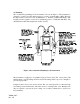
SENSOR (TOP VIEW) FLOW THROUGH CUVETTE ULTRASONIC SPRING CONNECTIONS ULTRASONIC TRANSDUCER Figure 6: Operational parts of the Ultrasonic Cleaning System 8.3 RS-485 Outputs The TB500 has the capability to operate in three different RS-485 modes for all models. Included is a mode for interfacing into the Online Scada software package (section 8.3.1 below), and a simple communication mode. A third operating mode is the Modbus communications.
The TB500 will respond with: • The same attention character “:” in ASCII or 3A Hex • The address of the TB500 • The Reading • The Unit (NTU) A sample communication would look like this: (Master computer requesting a report from address #1) : 1 CRLF (TB500 set to address #1 Response) :001 0.0249 NTU 8.3.3 Modbus Communication Modbus protocol communication is operational on all models. The Modbus information is covered in a separate manual. 8.
9.0 Troubleshooting & Maintenance 9.1 TB500 Fault Detection The TB500 performs continuous diagnostic monitoring. In the TB500 there are three levels of fault detection; warnings, errors and failures. Any faults are displayed in a queue form in the bottom row of the LCD. A warning is simply a screen indication of a problem. No alarms are activated. If the desiccant alarm is turned off and the desiccant becomes saturated, a screen warning of DESC will appear.
9.3 Diagnostic Chart Symptom Cause Cure Lower display shows MA 4-20 mA loop open Lower display shows DESC Desiccant pouch bad Lower display shows LAMP Lamp failed Lower display shows FLOW Sample flow has stopped Lower display shows FAIL Readings are higher than expected Major system fault (1) Bubbles in solution Check wiring. See sections 3.3.4 and 7.2 Change desiccant pouch. See section 10.2 Replace lamp. Refer to section 10.3 Restore flow.
10.0 Routine Maintenance 10.1 Cleaning the Flow Through Cuvette Measurement cuvettes used for both grab sample and the flow through should be clean and free of marks or scratches. Cleaning is accomplished by cleaning the interior and exterior with a detergent solution and then rinsing several times with distilled or deionized water. The cuvette can be replaced by first shutting off the flow using the provided shutoff clamp; unscrewing the old cuvette and replacing with a fresh clean one. 10.
11.0 Accessories and Replacement Parts List The items shown below are recommended accessories and replacement parts. Accessory Electronic Service Module For TB502 Electronic Service Module For TB504 Catalog Number White Light Infrared TB502TB502-ESMIR ESMWL TB504ESMWL TB504-ESMIR Calibration Kit, Full Range, .
12.0 Warranty Global Water Instrumentation, as vendor, warrants to the original purchaser of this instrument that it will be free of defects in material and workmanship, in normal use and service, for a period of one year from date of delivery to the original purchaser. Global Water’s, obligation under this warranty is limited to replacing, at its factory, the instrument or any part thereof.