
Manual

OPERATION
Page 6
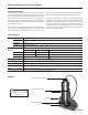
Flow Range (GPM)
1-1/2" 2" 3" 4" 6" 8"
Min 1.1 2.1 4.6 7.9 18 31
Max 190 314 691 1190 2700 4680
Minimum Flow. As with any other ow sensor, there is a rate
below which the TX80-Series sensor cannot read. Check the
ow rate table below for the minimum ow rate detectable by
the sensor for a given pipe size.
Calibration (“K-factor”). The K-factor represents the actual
number of pulses per gallon the meter produces during a ow
test. This number can be entered into your electronic control to
make it read properly. If the TX80-Series meter is ordered with
a tee tting, it is factory-calibrated in the tting and the K-factor
is indicated on the side of the tting. For saddle and weldolet
K-factors, see the K-factor calculator located at the bottom of
the www.seametrics.com home page.
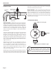
10031295
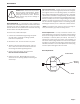
MF81T-P200
K: 53.6
Find Your K-Factor Here
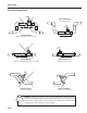
Modularity. Any of the TX80-Series ow sensors can have elec-
tronic modules mounted directly to them, either at the time
of order or by adding an adaptor kit in the eld (part number
MK10). Alternatively, the ow sensor and indicator or transmit-
ter can be installed remote from each other. The FT420 is an
indicating transmitter (rate, total, 4-20 mA output), and the
AO55 is a blind 4-20 mA transmitter. For data logging, add
the DL76. The FT520, which provides batching and other func-
tions, is suitable for remote installation.
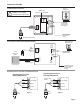
Output. The output is a current-sinking pulse (square wave)
compatible with many controls in addition to the Seametrics
indicators and transmitters. The most common of these are
water treatment controllers and programmable logic control-
lers (PLC’s). For these units, it is sometimes necessary to
provide a pull-up resistor if the controller does not provide for
a current-sinking output. (See the section on “Connecting to
PLC’s and other controllers” before connecting to a non-Sea-
metrics control.)
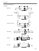
Fittings. Since the TX80-Series sensors are not adjustable,
they must be purchased with ttings appropriate to the appli-
cation. The TX81 is sized for ttings of 1 1/2” to 3”. The TX82
is for ttings of 4” and 8”. Each tting insures that the ow
sensor is installed at the correct point. Every ow sensor and
every tee tting is wet calibrated. Saddle ttings are normally
not wet calibrated, because they are eld-installed on a pipe.
In PVC however it is possible to order a saddle pre-installed on
a standard length of pipe, in which case the entire assembly is
wet-calibrated. For all other saddles, the K-factor (pulses per
gallon) is established through testing with various standard
schedules of pipe and provided with the saddle.