
Operating Manual


VX410/420 Series
Operating Manual
2/9
Vertex Standard Co., Ltd.
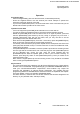
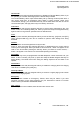
Controls & Connectors
・ LED Indicator
Glows Green: Monitor on
Blinks Green: Busy Channel (or SQL off)
Glows Red: Transmit
Blinks Red: Battery Voltage is low
Blinks Yellow: Receiving a Selective Call
・ Antenna Jack
・ PTT(Push To Talk)Switch
・ Side1 key(Case side)
・ Side2 key(Case side)
・ CH(Channel) Selector
・ VOL/PWR knob
・ LCD (VX-427 only)
・ A Key (VX-427 only) with 16 keys
・ B Key (VX-427 only) with 16 keys
・ C Key (VX-427 only) with 16 keys
・ D Key (VX-427 only) with 16 keys
・ MIC/SP Jack (External Mic/Earphone)
・ Speaker
・ Internal Microphone
・ Battery Pack Latch
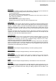
Before You Begin
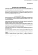
Battery Pack Installation and Removal
・ To install the battery, hold the transceiver with your left hand, so your palm is over the
speaker and your thumb is on the top of the belt clip. Insert the battery pack into the
battery compartment on the back of the radio while titling the Belt Clip outward, then close
the Battery Pack Latch until it locks in place with a “Click”.
・ To remove the battery, turn the radio off and remove protective cases. Open the Battery
Pack Latch on the bottom of the radio, and then slide the battery downward and out from
the radio while unfolding the Belt Clip.
Caution!: Do not attempt to open any of the rechargeable Ni-Cd packs, as they could
explode if accidentally short-circuited.
Low Battery Indication
・ As the battery discharges during use, the voltage gradually becomes lower. When the
battery voltage reaches 6.3 Volts, substitute a freshly charged battery and recharge the
depleted pack. The TX/BUSY indicator on the top of the radio will blink red when the
battery voltage is low.
・ Avoid recharging Ni-Cd batteries often with little use between charges, as this can
degrade the charge capacity. We recommend that you carry an extra, fully-charged pack
with you so the operational battery may be used until depletion (this “deep cycling”
technique promotes better long-term battery capacity)
FCC ID: K6610504420/IC ID: 511B-10504420