VHF/UHF C4FM/FM 50W AMS DIGITAL REPEATER DR-1X FR DR-1XE FR Operating Manual
Contents About this manual.................................................. 2 Introduction............................................................. 1 Features of this repeater...................................... 1 About the touch panel.......................................... 1 Safety Precautions (make sure to read these).... 1 Setting up the Repeater......................................... 3 Safety measures for installation........................... 3 Installing the repeater......................
Introduction Features of this repeater Congratulations on your purchase of the DR-1X Yaesu 144/430MHz Dual Band Dual Receive C4FM/FM Digital Repeater. The YAESU DR-1X is a C4FM digital / analog FM dual mode repeater that covers the VHF and UHF amateur radio bands. DR-1X incorporates the use of Analog FM communication integrated with the C4FM digital communication through its unique AMS capability. r r r r r The Dual-band repeater is equipped with the VHF and the UHF Amateur radio bands.
WARNING Do not use voltages other than the specified power supply voltage. Doing so may result in fire and electric shock. Do not transmit continuously for long periods of time. This may cause the temperature of the main body to rise and result in burns and failures due to overheating. Do not dismantle or modify the device. This may result in injury, electric shock and equipment failure. When smoke or strange odors are emitted from the radio, turn off the power and disconnect the power cord from the socket.
Setting up the Repeater Safety measures for installation Note the following precautions when installing this repeater: Use good engineering, proper grounding and protective devices to protect the repeater from power surges, lightening and electrical damage via the power and external antenna connections. Do not install the repeater in a place where there is extreme vibration, where there is a lot of dust, excessive humidity or high temperature, or where it is exposed to direct sunlight.
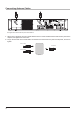
Connecting Antenna Cables The figure above shows the rear panel of the DR-1X. 1 When using a duplexer, plug the coaxial cables from the TX ANT and RX ANT terminals into the jacks of the duplexer, and tighten the connectors. 2 Plug in the terminal of the coaxial cable connected to the antenna into the jack of the duplexer, and turn to tighten.
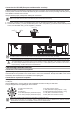
Connecting the Power Supply Connection for DR-1X (US and Asian versions) zz Main power Use an AC outlet capable of supplying AC 100-240V at 50 or 60Hz. 1 Insert the socket of the provided AC power cord into the AC IN jack at the rear of the repeater. 2 Insert the plug of the provided AC power cord into the AC outlet. zz Backup power For uninterrupted operation during power failures, a 13.
Connection for DR-1XE (European and Australian versions) Follow the outline in the illustration regarding the proper connection for the required External Power Supply. The DC power connector for the DR-1XE must only be connected to a DC source providing 13.8V DC (±15 %), and capable of at least 10A of current. Always observe proper polarity when making DC connection. Make sure to switch OFF the power of the external power source before connecting.
Accessories and Options Supplied Accessories AC Power Cord (T9017882)ø1 ....................................................................................................................... DC Power Cord with Fuse (T9026115) ............................................................................................................ Spare Fuse 15 A (Q0000075) ................................................................................................................... 5 A (Q0000143)ø1 ...............
Rear Panel DR-1X (US and Asian versions) DR-1XE (European and Australian versions) TX Antenna Terminal (N-type connector, 50 ohms) Connect to the transmitting antenna (downlink) with the coaxial cable. Cooling fan RX Antenna Terminal (N-type connector, 50 ohms) Connect to the receiving antenna (uplink) with the coaxial cable. FUSE Holder (15A/ 32V) A 15A fuse for the DC power supply through the BACKUP / DC IN jack is attached.
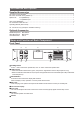
1. Initial set up Turn the power on 1 Press the POWER switch. The power will be switched ON, and the power supply monitor (LED indicator) will illuminate. zzWhen the power is supplied from the AC IN jack, the indicator illuminates in green (DR-1X only). zzWhen the power is supplied through the BACKUP terminals / DC IN terminal (13.8V DC), the indicator illuminates in red. The operation mode screen will appear on the display.
2. Set up Operation Mode When the Power Switch is turned ON, Operation Mode screen appears. This screen is for normal operation. The DR-1X could be set up with two frequencies for the uplink and the downlink and also different operation modes for each frequency. RX (uplink) TX (downlink) REMOTE To receive Analog FM and Digital C4FM signals simultaneously, set RX to [AUTO] mode.
3. Set up Frequency SETUP RX (uplink) UP Ver.1.xxx EXP A1 LINK 8 7 PANEL1.XX DSP4.XX LINK DOWN 3 7 TX (downlink) BACK V/ M SQL Tx PW R HI F Status display area A green bar is displayed during receive when signals are detected. The bar will not be displayed when the squelch is turned on and the received signal level is below the squelch level. VOL/SQL level display S-meter level display PO-meter level display Firmware Version Information Ver. x.
4. Set up Other Functions Adjusting the squelch level zzWhen the squelch level is set to “open” the repeater will transmit, so the TX output must be connected to the duplexer and antenna. zzUse extreme caution when making the squelch adjustment or measurement with a signal generator. Do not connect the signal generator to the duplexer antenna port. To avoid damage to the test equipment, always connect the signal generator directly to the RX antenna connector on the DR-1X.
5. Base mode operation The repeater can be used as a VHF/UHF base station by connecting an optional MH-48A6JA or MH-42C6J microphone to the “MIC” jack on the front panel.
6. Set up DG-ID Number Digital Group Identification (DG-ID) The Digital Group Identification (DG-ID) feature controls access to the repeaters by using the two-digit numbers from 01 to 99. This feature is similar to the CTCSS function used in the Analog FM mode. The DG-ID number 00 detects signals with all ID numbers. The default DG-ID number is set to “00”. All the C4FM digital stations' uplink signal may be operated.
5 Touch [Group Name] twice. The character input screen appears. Group 4 DG-ID >50 DG-ID Group Name 6 Input the name to be registered to the DR-1X repeater. Up to 10 characters may be input. 7 Touch [ENT]. The input characters are registered and operation returns to the group setting screen. 8 Touch [BACK] 4 times. The screen returns to the operation mode screen.
7. Set up DP-ID Digital Personal Identification (DP-ID) Digital Personal Identification (DP-ID) is the digital ID number each transceiver is programmed with. The system manager may operate the DR-1X repeater functions, by registering the DG-ID number of the controlling C4FM digital transceiver to the DR-1X. In order to use the DP-ID feature, update the C4FM digital transceivers to the latest firmware compatible with the DP-ID feature.
Delete the registered DP-ID 1 Touch [SETUP] or [B SETUP] to display the frequency set up screen, then touch [F] on the bottom of the screen. SETUP Ver.1.xxx EXP A1 2 Touch [ID MODE] to select the “DP-ID”. UP LINK Touching [ID MODE] switches the setting as follows: à “DP-ID” à “DG-ID” à “DP-ID” à The DP-ID display returns to the DG-ID display in about 5 seconds.
8. Remote Controls Setting the remote control •• Remote control of the DR-1X repeater can be performed in either C4FM digital mode or analog FM mode. For C4FM digital mode, use the FTM-400D, FTM-100D, FTM-3200D or FTM-3207D transceiver. For security reasons, we recommend using a mobile C4FM transceiver with the DP-ID that is registered to the DR-1X repeater. •• Remote operation sends commands on the uplink frequency.
C4FM DIGITAL CONTROL •• Set the operation mode to “AUTO” or “FIX NORMAL”. •• The transceivers compatible with the remote-control are the FTM-400D, FTM-100D, FTM-3200D and FTM3207D. •• Remote control with C4FM digital can be done only when the transceiver DP-ID has been registered to the DR-1X in advance. Remote operation cannot be performed with a transceiver when the DP-ID has not been registered, so you can securely manage repeaters.
Change the remote command To change the factory command code of C4FM digital 1 Touch [SETUP] on the operation mode screen. SETUP UP Ver.1.xxx EXP A1 LINK The setup mode screen will appear. 2 Touch [F] on the setup mode screen. The setup menu will appear. 3 Touch [MODE/REMOTE]. The menu list will appear. DOWN ��������� LIDI MODE NK SQL MODE/REMOTE R-OFF T-OFF BACK V/ M 4 Touch [COMMAND] twice. The command list will appear.
To change the factory command code of analog FM 1 Touch [SETUP] on the operation mode screen. SETUP UP Ver.1.xxx EXP A1 LINK The setup mode screen will appear. 2 Touch [F] on the setup mode screen. The setup menu will appear. 3 Touch [MODE/REMOTE]. The menu list will appear. DOWN ��������� SQL R-OFF T-OFF LIDI MODE NK DG-ID MODE/REMOTE BACK V/ M 4 Touch [COMMAND] twice. The command list will appear.
9. Actual remote control procedure Remote Control for C4FM Digital When controlling remotely with the FTM-400D 1 2 3 4 Please confirm that the FTM-400D DP-ID is registered on the DR-1X repeater. Tune the transmit frequency of the FTM-400D to the uplink frequency of the DR-1X. Set the FTM-400D to the digital mode, then press and hold the “Û” key on the microphone (MH-48A6JA). “REMOTE REC/PLY” is displayed on the top of the FTM-400D screen, the remote-control is available.
When controlling remotely with the FTM-3207D 1 2 3 4 Please confirm that the FTM-3207D DP-ID is registered on DR-1X repeater. Tune the transmit frequency of the FTM-3207D to the uplink frequency of the DR-1X. Set the FTM-3207D to the digital mode, then press and hold the “Û” key on the microphone (MH-48A6JA). “REMOTE” is displayed on the screen of the FTM-3207D, the remote-control is available. •• Cancelling the remote-control, press the “Û” key on the microphone (MH-48A6JA).
10. Set Up Various Functions Using the setup menu, the various functions of the repeater can be customized to match the desired applications. Items to be adjusted can be selected from the respective lists, and the settings entered or selected that are appropriate for the intended repeater operation. 1 Touch [SETUP] on the operation mode screen. The setup mode screen will appear. 5 Touch [▲] or [▼], or touch the item repeatedly. The set value will change each time it is touched. SETUP UP Ver.1.
Setting the tone signals for analog FM mode Setting the tone frequency 1 Touch [SETUP] then touch [F]. 2 Touch [SIGNALING], then touch [TONE SQL FREQ]. 3 Touch [▲] or [▼]. The set value will change each time [▲] or [▼] is touched. 4 Touch [BACK] 3 times. The setting is determined and the display will return to the operation mode screen.
Setting the SQL TAIL LENGTH Enables setting the time duration of the downlink transmit after the uplink signal ceases. SETUP 1 Touch [SETUP], then touch [F], and then touch [TIMER]. UP LINK 2 Touch [SQL TAIL LENGTH]. 8 7 The set value will change in the following sequence each time [SQL TAIL LENGTH], [▲], or [▼] is touched. NK D O W N LIDI MODE TIMER ID ANNOUNCE ��������� DG-ID DEVIATION à “0ms” à “50ms” à “100ms” à ......................
Set the tone signal type for analog FM mode 1 Touch [SETUP], then touch [F], and then touch [SQL]. 2 Select [RX SQL] to set the tone signal type during reception, or select [TX SQL] to set the tone signal type during transmission. 3 Touch [▲] or [▼]. The setting will change in the following sequence each time [▲] or [▼] is touched.
5 Touch [PASSWORD] twice. The character input screen will appear. The touched character will be displayed at the top of the screen. •• Four numeric characters can be entered. •• The cursor in the input field moves left or right when [|] or [|] is touched. •• After completing the input password, the character input screen automatically disappears and the input password is set. 6 Touch [BACK] 4 times. The setting is determined and the display will return to the operation mode screen.
11. Restoring Default Settings (Factory Reset) 1 Turn the DR-1X OFF. 2 Press and hold in the [SETUP] button while turning the repeater ON. POWER SETUP Continue pressing the [SETUP] button until the operation mode screen appears on the display. 3 Touch [SETUP]. The setup mode screen will appear. REMOTE 4 Touch [F] in the setup mode screen. The setup menu will appear. 5 Touch [F]. The reset confirmation screen will appear. SETUP UP Ver.1.xxx EXP A1 LINK 8 7 PANEL1.XX DSP4.
12. Connect to the HRI-200 node station To use WIRES-X with DR-1X, connect HRI-200 directly to the 10-pin plug on the back of the DR-1X. Alternatively, there is a method the HRI-200 Node station may be located in a place different from the repeater site.
Connecting HRI-200 to DR-1X The following explains how to connect HRI-200 directly to DR-1X. 10 pin plug Mini-DIN digital cable (supplied with HRI-200) 10 pin plug Type B plug LAN cable (sold separately) Type A plug To the Internet USB cable (supplied with HRI-200) Change the repeater to the HRI mode 1 Turn the DR-1X power OFF. 2 While pressing and holding the [SETUP] button, press the [POWER] switch. 3 While the “YAESU” logo is being displayed, release the [SETUP] button.
Return to REPEATER mode from HRI mode 1 Turn the DR-1X power OFF. 2 While pressing and holding the [SETUP] button, press the [POWER] switch. 3 While the “YAESU” logo is being displayed, release the [SETUP] button. “REPEATER MODE” will appear on the display. 4 Touch [OK?]. The operation mode screen will appear on the display.
13. Remote Operation with External Controller Repeater operation may be controlled remotely by connecting an external controller through the [CONTROL I/O] connector at the back of the repeater.
Pin No Pin Name I/O 1 EXT I/O Input 2 PTT Input 3 CTCSS/DCS (PKSQL) Output 4 SQL DET (Noise SQL) Output 5 GND GND 6 TONE IN Input 7 AF IN Input Descriptions [L] GND: Remote mode [H] OPEN: Repeater mode [L] GND: EXT PTT ON [H] OPEN: EXT PTT OFF When this pin is pulled low by an external device, it keys the repeater transmitter. On signaling while controlling the external PTT: Pin 6 (TONE IN) ... Valid Pin 7 (AF IN) ...
Pins 6, 7, 8, and 9 Functions Controlled by Operation Mode Pin No Pin Name Receive Mode Digital 6 TONE IN Analog Digital 7 AF IN Analog Digital 8 DISC OUT Analog Digital 9 AF OUT Analog In Repeater / Remote Mode Invalid Invalid Invalid Invalid Invalid Discriminator output Demodulated digital audio output Analog audio output Even when using the DR-1X with an external controller, the COR, analog and digital IDs, TOT, DCS/CTCSS, TX power, etc. are already controlled by the DR-1X internal control.
Setting to connect the repeater controller S-COM7330 Set up instructions to interface the Triple Repeater Controller S-COM7330 with the DR-1X. Modification of S-COM7330 1 Remove the 6 screws from each side and 2 screws from the top cover of the S-COM7330, then remove the top cover. 2 Change Jumper pin J10C or J11C or J3C and adjust the semi fixed. AF volume gain up for RX1 or RX2 or RX3. 3 Command Settings.
Connecting S-COM7330 S-COM7330 PORT 3 PORT 2 PORT 1 +- INIT RESET ID RS232-2 RS232-1 DC 9V-36V This connection needs Repeater 1 programming of S-COM7330.
14. Installation of the Optional Accessories Installing the optional Voice Guide Unit FVS-2 1 Turn the DR-1X [POWER] switch to “OFF”. 2 Disconnect all the cables from the DR-1X. 3 Remove the 4 screws from each side and 7 screws from the top cover of the DR-1X, then remove the top cover. Figures in this page show the outline of the DR-1X. 4 Referring to Figure 1, remove the 4 screws from the top cover of the RX-UNIT, then remove the top cover.
15. Specifications zzGeneral Frequency range Channel steps Emission type : 144 to 146 MHz, 430 to 440 MHz or 144 to 148 MHz, 430 to 450 MHz : 5 / 6.
YAESU LIMITED WARRANTY Limited Warranty is valid only in the country/region where this product was originally purchased. On-line Warranty Registration: Thank you for buying YAESU products! We are confident your new radio will serve your needs for many years! Please register your product at www.yaesu.
This equipment has been tested and found to comply with the limits for a Class B digital device, pursuant to Part 15 of the FCC Rules. These limits are designed to provide reasonable protection against harmful interference in a residential installation. This equipment generates, uses and can radiate radio frequency energy and, if not installed and used in accordance with the instructions, may cause harmful interference to radio communications.
Copyright 2017 YAESU MUSEN CO., LTD. All rights reserved. No portion of this manual may be reproduced without the permission of YAESU MUSEN CO., LTD. YAESU MUSEN CO., LTD. Tennozu Parkside Building 2-5-8 Higashi-Shinagawa, Shinagawa-ku, Tokyo 140-0002 Japan YAESU USA 6125 Phyllis Drive, Cypress, CA 90630, U.S.A. YAESU UK Unit 12, Sun Valley Business Park, Winnall Close Winchester, Hampshire, SO23 0LB, U.K.