INSTRUCTION MANUAL FC-7 YAESU MUSEN CO., LTD C.P.O.
YAESU FC-700 ANTENNA COUPLER GENERAL The FC-700 is an ultra-compact antenna tuner for thé FT-77 transceiver. Designed for opération on thé 80 through 10 meter amateur bands (including WARC bands), thé FC-700 will provide a 50-ohm load to thé transceiver when thé feedpoint impédance of thé antenna System is within thé approximate range of 10 ohms to 250 ohms. The FC-700 includes a built-in SWR and power meter, providing 15 watt and 150 watt scales.
SPECIFICATIONS Frequency coverage: 3.5 3.5-4.0 MHz 7 7.0-7.5 MHz 10 10.0-10.5 MHz 14 14.0-14.5 MHz 18 18.0-18.5 MHz 21 21.0-21.5 MHz 24.5 24.5-25.0 MHz 28 28.0-29.7 MHz Insertion loss: 0.5 dB max. Rear panel antenna connection: UHF type connecter Dimensions: 2 3 8 ( W ) x 5 5 ( H ) x 180(D)mm Weight: Input impédance: 2.0kg 50 ohms SWRcalibration: To5:l SWR Max. variation in load impédance: approx.
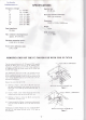
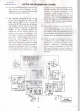
FRONT PANEL CONTROLS AND SWITCHES (1) Meter The meter provides indication of thé SWR or power level. established by thé BAND switch and LOAD control. The TUNE and LOAD controls are adjusted for minimum SWR. (2) (5) BAND SWR SET The BAND selector sélects thé appropriate tap on thé main tuning inductor for thé band in use. This control sets thé sensitivity of thé SWR meter. (3) Function Switches REF/FWD This switch sélects forward or reflected power indication on thé meter.
REAR APRON (1) be connected hère, to supply thé meter lamp on thé front panel of thé FC-700. ANT This is a standard UHF connecter for thé antenna feedline. (4) (2) GND INPUT Connect thé coaxial cable to thé FT-77 ANT jack at this point. Connect a good earth ground at this point. (3) DC 8V The DC8V Une from thé FT-77 transceiver should FT-77 Séries °o o nnanno DDDDDDP.
INSTALLATION When using a transceiver other than thé- FT-77, be absolutely certain to observe thé proper polarity and level of thé voltage applied to thé rear panel DC8V jack. Do not exceed 8 volts DC, nor apply AC power of any kind, to this jack. Our warranty does not cover damage caused by improper power Connect thé antenna to thé rear panel ANT jack, and connect a 50-ohm coaxial cable between thé FT-77 and thé FC-700. Connect thé DC cable between thé DC8V jacks of thé FC-700 and thé FT-77.
ANTENNA MATCHING PROCEDURE THIS SECTION SHOULD BE STUDIED CAREFULLY BEFORE USING THE FC-700. WHILE A STRAIGHTFORWARD PROCEDURE, ANTENNA MATCHING WITH A COUPLER SUCH AS THE FC-700 INVOLVES A LOGICAL PROGRESSION OF STEPS, AND FAMILIARITY WITH THE TOTALITY OF THE FOLLOWING SECTION WILL AVOID POSSIBLE DAMAGE TO THE EQUIPMENT CAUSED BY INCORRECT (1) Set up thé FT-77 or other transceiver for normal opération. Set thé DUMMY/ANT switch to DUMMY to sélect thé built-in dummy load.
(5) Once thé initial procédure has been followed to yield a near-perfect match, thé transmitter may be adjusted for tu 11 power, and thé FC-700 LOAD and TUNE controls-may be adjusted to yield zéro deflection of thé SWR meter. When thé SWR meter is not calibrated Witll thé SWR SET control. it will not accurately read thé SWR, but it will indicate minimum reflected power. Do not exceed thé maximum key-down time stipulated for your transmitter, BAND FREQ TUNE LÔAD 3.5 MHz 4.5 7.0 4.0 MHz 5.5 7.5 7.
NOTES ON ANTENNA MATCHING (1) It is very important that thé maximum time limits during tune-up conditions for thé transmit ter are not exceeded when thé transmitter is being used at full power. (2) Any matching perfbrmed by thé FC-700 in thé shack will hâve no effect on thé lOSSeS due to SWR on thé coaxial Une between thé FC-700 coupler and thé antenna.
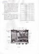
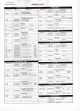
PARTS LIST ! MAIN CHASSIS Symbol No. VR01 RELAY UNIT Part No. Description J6080070 POTENTIOMETER VM10A949C-50knB Symbol No. Part No. C0021240 F0002124 Description P.C.B with Components Printed Circuit Board DIODE VC01 VC02 K90000029 K90000028 VARIABLE CAPACITOR YB-290, 290pF YB-430, 430pF MOI M0290020 METER SY-50 SOI N0190069 D201 G2090001 C201 K13170473 RL201 M1190025 10D1 CAPACITOR DC 200MA SWITCH Q5000011 RELAY MR-31 Wrapping terminal C SRS4.
YAESU v - E8285100 (008X-IS)