
Operation Manual

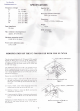


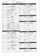

SPECIFICATIONS
Frequency
coverage:
3.5
7
10
14
18
21
24.5
28
3.5-4.0
MHz
7.0-7.5
MHz
10.0-10.5
MHz
14.0-14.5
MHz
18.0-18.5
MHz
21.0-21.5
MHz
24.5-25.0
MHz
28.0-29.7
MHz
Input
impédance:
50
ohms
Max.
variation
in
load
impédance:
approx.
10-250
ohms
Insertion
loss:
0.5 dB
max.
Rear
panel
antenna
connection:
UHF
type
connecter
Dimensions:
238(W)x55(H)x
180(D)mm
Weight:
2.0kg
SWRcalibration:
To5:l
SWR
Maximum transmitter
power:
150WRF@50ohms
Power
meter
calibration
scales:
15
W,
150W
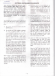
MODIFICATION
OF THE
FC-700
FOR USE
WITH
IHE
FT-747GX
The
relay
and
panel
lamp
in
(he
FC-700
require
8
VDC.
supplîed
through
thé
DC8V jack
on
Ihe
rear
of
thé
Antenna
Tuner.
Although
it is
possible
10
use
thé
FC-700
without
modification
by
supplying
8V.
from
an
external
source,
thé
FT-747GX
does
not
offer
such voltage.
This modification allows
thé
FC-700
to be
operated
from
thé
DG13.5V
outpui
jack
on
thé
rear panel
of Ihe
FT-747GX.
so
that
thé
FC-700
can be
switched
on and
off
with
thé
tran^eiver.
Be
sure
to
change
thé
DC8V label
on
thé
FC-700
to
DC13.5V after
making
this
modification.
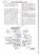
Remove
thé
covers
from
thé
FC-700.
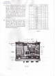
(1)
Referring
10
Figure
I.
remove
thé
two
BLACK
wires
from
thé
meter lamp
terminal,
and
connect
thé
one
from
thé
DC8V
jack
to
thé
solder
lug
near
thé
mêler
(thé
other
is
not
used).
(2)
Install
a
56-ohm.
2-watt
resistor
between
thé
meter lamp
terminal
and
thé
solder
lug
with
thé
BLACK
wire.
(3)
Referring
to
Figure
2,
remove
thé
BLUE
wire
from
thé
terminal
post
on
thé
RL
Unit.
(4)
Connect
one end of a
100-ohm,
4-watt
resistor
to
thé
terminal
post.
and
connecl
thé
BLUE wire
to
thé
other
end of
thé
resistor.
Modification
is
complète. Replace
thé
covers. relabel
ihe
DC8V
jack DCI3.5V,
and
connect
this
jack
to
thé
+13.5V
jack
on
thé
FT-747GX.
Install
a
56-ohm,
2W
Resistor
Remove
&
reconnect
thé
BLACK
wire
Figure
1
Installa
lOO-ohm,
I/2W
Resistor
Remove
&
reconnect
thé
BLUE
wire
Figure
2
- 2 -