
Operation Manual


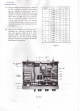
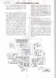

FRONT PANEL CONTROLS
AND
SWITCHES
(1)
Meter
The
meter
provides
indication
of
thé
SWR or
power
level.
(2) SWR SET
This
control
sets
thé
sensitivity
of
thé
SWR
meter.
(3)
Function
Switches
REF/FWD
This switch sélects
forward
or re-
flected
power
indication
on
thé
meter.
SWR/PO
This
switch
sélects
indication
of
thé
SWR
or
power output
on
thé
meter.
15W/150W
This
switch
sélects
indication
of
thé
output power
level
scales:
15 or
150
watts
full
scale.
(4)
TUNE
The
TUNE control drives
a
variable capacitor
which
provides capacitive adjustment
of
thé
coupl-
ing
between
thé
transmitter
and
thé
impédance
established
by
thé
BAND
switch
and
LOAD
control.
The
TUNE
and
LOAD
controls
are
adjusted
for
minimum
SWR.
(5)
BAND
The
BAND selector sélects
thé
appropriate
tap on
thé
main tuning inductor
for
thé
band
in
use.
(6)
DUMMY/ANT
This
switch sélects either
thé
antenna
or
connec-
tion
to
thé
50-ohm
dummy
load.
When
thé
built-in
dummy
load
is
selected,
thé
antenna coupler tuning
controls
are
still
in
thé
line,
so
preliminary
adjust-
ment
of
thé
coupler
can be
performed.
When
this
button
is
pressed
and
thé
BAND selector
is set to
thé
THRU
position,
only
thé
dummy
load
and
meter remain
in
thé
circuit.
(7)
LOAD
The
LOAD
control
drives
a
variable
capacitor
which
adjusts
thé
coupling
between
thé
antenna
feedline
and
thé
main
BAND inductor.
- 3 -