
Operation Manual


NOTES
ON
ANTENNA
MATCHING
(1)
It
is
very important
that
thé
maximum time
limits
during
tune-up conditions
for
thé
transmit
ter
are not
exceeded when
thé
trans-
mitter
is
being used
at
full
power.
(2)
Any
matching
perfbrmed
by
thé
FC-700
in
thé
shack
will
hâve
no
effect
on
thé
lOSSeS
due to SWR on
thé
coaxial
Une
between
thé
FC-700
coupler
and
thé
antenna.
The
operator
should consult
one of
thé
popular antenna handbooks
to
détermine
whether
or not
matching between
thé
coaxial
line
and
thé
antenna must
be
per-
formed
at
thé
antenna.
For
example,
a
100-
foot length
of
RG8A/U
coax typically
has a
loss
(with
1:1 SWR
between
it and
antenna)
of
less
than
1 dB at 21
MHz.
If
this
line
is
operated with
a
3:1
SWR due to a
low
or
high
antenna impédance,
thé
loss
due to SWR
will
increase roughly
0.5
dB,#n
imperceptible
dégradation
as
compared
to
thé
1:1
condition.
In
this case, attempts
to
reduce
thé
3:1 SWR
at
thé
antenna
end
would
serve
no
useful
purpose
as far as
reducing losses
in
thé
coax,
through
matching with
thé
FC-700
would
improve
thé
impédance presented
to
thé
transmitter output
circuitry-
However,
if a
500-foot length
of
thé
above coax were used
instead
of
oniy
ioo
feet,
somewliat
more
than
1 dB of
loss
would
occur
in
thé
ooflv
due
to
thé
3:1
SWR,
possibly
justifying further
matching
attempts
at
tlic
untciinu.
(3)
When
using
a
transceiver
such
as
thé
FT-77
which
has
protection
for
thé
output tran-
sistors
against high SWR,
it can be
seen that
thé
matching action
of
thé
FC-700
will
ensure
that
a
50-ohm
load
is
presented
to
thé
output
circuitry, thus
ensuring
full
transmitter
power.
(4) It may be
useful
for
thé
operator
to
record
in
a
notebook
thé
proper TUNE
and
LOAD
positions
for a
particular antenna
for
quick
référence.
Alternatively,
appropriate
labels
may
be
fabricated
and
applied
to
thé
FC-700
front
panel showing
thé
proper positions
of
thé
TUNE
and
LOAD
controls
for a
particular
frequency.
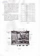
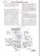
JOf
FC-70Q
CIRCUIT
DIAGRAM
- 8 -