FM TRANSCEIVER FT-1802M OPERATING MANUAL VERTEX STANDARD CO., LTD. 4-8-8 Nakameguro, Meguro-Ku, Tokyo 153-8644, Japan VERTEX STANDARD US Headquarters 10900 Walker Street, Cypress, CA 90630, U.S.A. YAESU EUROPE B.V. P.O. Box 75525, 1118 ZN Schiphol, The Netherlands YAESU UK LTD. Unit 12, Sun Valley Business Park, Winnall Close Winchester, Hampshire, SO23 0LB, U.K. VERTEX STANDARD HK LTD. Unit 5, 20/F.
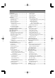
Contents Introduction ...................................................... 1 Specifications .................................................... 2 Accessories & Options ..................................... 3 Supplied Accessories ..................................... 3 Optional Accessories ...................................... 3 Installation ........................................................ 4 Preliminary Inspection ................................... 4 Installation Tips ...........................
INTRODUCTION The Yaesu FT-1802M is a deluxe, rugged FM mobile transceiver providing high power output and outstanding receiver performance for the 144 MHz Amateur band. Included in the FT-1802M’s feature complement are: 50 Watts of power output, with selection of four power levels for every operating situation. Expanded receiver coverage: 136-174 MHz. Keyboard entry of operating frequencies from the microphone.
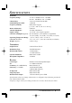
SPECIFICATIONS General Tx 144 - 146 MHz or 144 - 148 MHz Rx 144 - 146 MHz or 136 - 174 MHz Channel Step: 5/10/12.5/15/20/25/50/100 kHz Standard Repeater Shift: ±600 kHz Frequency Stability: Better than ±10 ppm [–4 °F to +140 °F (–20 °C to +60 °C)] Modes of Emission: F2D/F3E Antenna Impedance: 50 Ohms, unbalanced Supply voltage: 13.8 V DC ±15%, negative ground Current Consumption (typical): Rx: less than 0.7 A, less than 0.
ACCESSORIES & OPTIONS SUPPLIED ACCESSORIES Microphone MH-48A6J ...................................................................................................... 1 Mobile Mounting Bracket MMB-36 .................................................................................. 1 DC Power Cord w/Fuse (T9021715) .................................................................................. 1 Spare Fuse 15 A (Q0000081) ....................................................................................
INSTALLATION This chapter describes the installation procedure for integrating the FT-1802M into a typical amateur radio station. It is presumed that you possess technical knowledge and conceptual understanding consistent with your status as a licensed radio amateur. Please take some extra time to make certain that the important safety and technical requirements detailed in this chapter are followed closely.
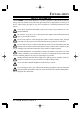
INSTALLATION SAFETY INFORMATION The FT-1802M is an electrical apparatus, as well as a generator of RF (Radio Frequency) energy, and you should exercise all safety precautions as are appropriate for this type of device. These safety tips apply to any device installed in a well-designed amateur radio station. Never allow unsupervised children to play in the vicinity of your transceiver or antenna installation.
INSTALLATION ANTENNA CONSIDERATION The FT-1802M is designed for use with antennas presenting an impedance of near 50 Ohms at all operating frequencies. The antenna (or a 50 Ohm dummy load) should be connected whenever the transceiver is turned on, to avoid damage that could otherwise result if transmission occurs accidentally without an antenna. Ensure that your antenna is designed to handle 50 Watts of transmitter power.
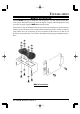
INSTALLATION MOBILE INSTALLATION The FT-1802M must only be installed in vehicles having a 13.8 Volt negative ground electrical system. Mount the transceiver where the display, controls, and microphone are easily accessible, using the supplied MMB-36 mounting bracket. The transceiver may be installed in almost any location, but should not be positioned near a heating vent nor anywhere where it might interfere with driving (either visually or mechanically).
INSTALLATION MOBILE INSTALLATION Mobile Power Connections To minimize voltage drop and avoid blowing the vehicle’s fuses, connect the supplied DC power cable directly to the battery terminals. Do not attempt to defeat or bypass the DC cable’s fuse - it is there to protect you, your transceiver, and your vehicle’s electrical system. Warning! Never apply AC power to the power cable of the FT-1802M, nor DC voltage greater than 15.8 Volts. When replacing the fuse, only use a 15-A fuse.
INSTALLATION BASE STATION INSTALLATION The FT-1802M is ideal for base station use as well as in mobile installations. The FT1802M is specifically designed to integrate into your station easily, using the information to follow as a reference. AC Power Supplies Operation of the FT-1802M from an AC line requires a power source capable of providing at least 10 Amps continuously at 13.8 Volts DC. The FP-1023 and FP-1030A AC Power Supplies are available from your Yaesu dealer to satisfy these requirements.
FRONT PANEL CONTROLS & SWITCHES VOL Knob This control adjusts the audio volume level. Clockwise rotation increases the volume level. SQL Knob This control is used to silence background noise on the receiver. It should be advanced clockwise just to the point where the noise is silenced (and the “ ” indicator on the display turns off), so as to provide the best sensitivity to weak signals. Microphone Jack Connect the supplied MH-48A6J Hand Microphone to this jack.
FRONT PANEL CONTROLS & SWITCHES [REV(DW)] Key During split-frequency operation, such as through a repeater, this key reverses the transmit and receive frequencies . Press and hold in this key for one second to activate the Dual Watch feature, described in the Operation chapter (“PRI” will be displayed on the LCD, indicating “Priority Channel” monitoring). : Using the Menu, the “Reverse” feature may be disabled in favor of one-touch access to the “Home” Channel. See page 33 for details.
MICROPHONE SWITCHES PTT Switch Press this switch to transmit, and release it to receive. Keypad These 16 keys generate DTMF tones during transmission. In the receive mode, these 16 keys can be used for direct frequency entry and/or direct numeric recall of the Memory channels. The [A], [B], [C], and [D] keys, on receive, replicate the functions of the front panel keys ([MHz(SET)], [REV(DW)], [LOW(A/N)], and [D/MR(MW)]). See the previous discussion.
REAR PANEL CONNECTORS 13.8V DC Cable Pigtail w/Fuse This is the power supply connection for the transceiver. Use the supplied DC cable to connect this pigtail to the car battery or other DC power supply capable of at least 10 Amperes (continuous duty). Make certain that the red lead connects to the positive side of the supply. The fuse is 15-A. ANT Coaxial Socket Connect a 144-MHz antenna to this type-M (SO-239) socket using 50-Ohm coaxial cable and a type-M (PL-259) plug.
BASIC OPERATION Hi! I’m R. F. Radio, and I’ll be helping you along as you learn the many features of the FT-1802M. I know you’re anxious to get on the air, but I encourage you to read the “Basic Operation” section of this manual as thoroughly as possible, so you’ll get the most out of this fantastic new transceiver. Now. . .let’s get operating! TURNING THE TRANSCEIVER ON AND OFF 1. To turn the transceiver on, press and hold in the PWR key for one second.
BASIC OPERATION FREQUENCY NAVIGATION 1) Tuning Dial Rotating the DIAL knob allows tuning in the pre-programmed steps. Clockwise rotation of the DIAL knob causes the FT-1802M to be tuned toward a higher frequency, while counter-clockwise rotation will lower the operating frequency. Press the [MHz(SET)] key momentarily, then rotate the DIAL knob, to change the frequency steps to 1 MHz per step. This feature is extremely useful for making rapid frequency excursions over the wide tuning range of the FT-1802M.
BASIC OPERATION TRANSMISSION To transmit, simply close the PTT (Push To Talk) switch on the microphone when the frequency is clear. Hold the microphone approximately 1” (25 mm) from your mouth, and speak into the microphone in a normal voice level. When your transmission is complete, release the PTT switch; the transceiver will revert to the receive mode. During transmission, the “ ” indicator will appear at the upper left corner on the display.
ADVANCED OPERATION WEATHER BROADCAST RECEPTION (USA VERSION) The FT-1802M includes a unique feature which allows reception of weather broadcasts in the 160-MHz frequency range. Ten standard Weather Broadcast channels are pre-loaded into a special memory bank. To listen to a Weather Broadcast Channel: 1. Press the Microphone’s [P4] button to recall the Weather Broadcast channels. 2. Turn the DIAL knob to select the desired Weather Broadcast channel. 3.
ADVANCED OPERATION LOCK FEATURE To order to prevent accidental frequency change or inadvertent transmission, various aspects of the FT-1802M’s keys and knob may be locked out. To lock out some or all of the keys, use the “Set” (Menu) mode, described below: 1. Press and hold in the [MHz(SET)] key for one second, then rotate the DIAL knob to select “26 LOCK.” 2. Press the [MHz(SET)] key, then rotate the DIAL knob to select the desired lockout combination. KEY: Just the front panel keys are locked out.
ADVANCED OPERATION CHANNEL STEP SELECTION Tuning steps are factory preset to default increments which are appropriate for the country to which this radio is exported. You may have a reason to use a different step size, however, and here is the procedure for changing the channel steps: 1. Press and hold in the [MHz(SET)] key for one second, then rotate the DIAL knob to select “50 STEP.” 2. Press the [MHz(SET)] key, then rotate the DIAL knob to select the desired step size (5/10/12.5/15/20/25/50/100 kHz). 3.
ADVANCED OPERATION RF SQUELCH A special RF Squelch feature is provided on this radio. This feature allows you to set the squelch so that only signals exceeding a certain S-meter level will open the squelch. To set up the RF squelch circuit for operation, use the following procedure: 1. Press and hold in the [MHz(SET)] key for one second, then rotate the DIAL knob to select “42 RF SQL.” 2.
REPEATER OPERATION The FT-1802M includes a host of convenience features which makes operation on amateur repeaters both efficient and enjoyable.
REPEATER OPERATION AUTOMATIC REPEATER SHIFT The ARS (Automatic Repeater Shift) feature in this transceiver allows easy and convenient repeater operation by automatically activating the repeater shift function whenever you tune to a standard repeater subband. The ARS function is preset at the factory to conform to the standards for the country to which it is exported. The ARS function is enabled at the factory. To disable it: 1.
REPEATER OPERATION SEPARATE TRANSMIT FREQUENCY MEMORIES (“ODD SPLITS”) All memory channels can store independent receive and transmit frequencies, to accommodate occasional non-standard offsets with greater frequency resolution than is available using the “standard” shift feature. 1. First store the receive (repeater output) frequency. In the VFO mode, tune the transceiver to the desired receive frequency. Now press and hold in the [D/MR(MW)] key on the front panel for one second. 2.
CTCSS/DCS/EPCS OPERATION CTCSS OPERATION Many repeater systems require that a very-low-frequency audio tone be superimposed on your FM carrier in order to activate the repeater. This helps prevent false activation of the repeater by radar or spurious signals from other transmitters. This tone system, called “CTCSS” (Continuous Tone Coded Squelch System), is included in your FT-1802M, and is very easy to activate. CTCSS setup involves two actions: setting the Tone Mode and then setting of the Tone Frequency.
CTCSS/DCS/EPCS OPERATION CTCSS OPERATION Your repeater may or may not re-transmit a CTCSS tone - some systems just use CTCSS to control access to the repeater, but don’t pass it along when transmitting. If the S-Meter deflects, but the FT-1802M is not passing audio, repeat steps “1” through “3” above, but rotate the DIAL knob so that “TONE” appears - this will allow you to hear all traffic on the channel being received.
CTCSS/DCS/EPCS OPERATION TONE SEARCH SCANNING In operating situations where you don’t know the CTCSS tone or DCS code being used by another station or stations, you can command the radio to listen to the incoming signal and scan in search of the tone being used. Two things must be remembered in this regard: You must be sure that your repeater uses the same tone type (CTCSS vs. DCS).
CTCSS/DCS/EPCS OPERATION EPCS (ENHANCED PAGING & CODE SQUELCH) OPERATION The FT-1802M includes an Enhanced CTCSS tone encoder/decoder and a dedicated microprocessor providing paging and selective calling features. This allows you to place a call to a specific station (Paging), and to receive calls of your choice directed only to you (Code Squelch). The paging and code squelch systems use two pairs of (alternately switched) CTCSS tones which are stored in the pager memories.
CTCSS/DCS/EPCS OPERATION EPCS (ENHANCED PAGING & CODE SQUELCH) OPERATION Activating the Enhanced Paging & Code Squelch System 1. Press and hold in the [MHz(SET)] key for one second, then rotate the DIAL knob to select “32 PAGER.” 2. Press the [MHz(SET)] key, then rotate the DIAL knob to set this Menu item to “ON.” 3. Press and hold in the [MHz(SET)] key for one second to save the new setting and exit to normal operation. 4.
CTCSS/DCS/EPCS OPERATION CTCSS/DCS/EPCS BELL OPERATION During CTCSS Decode, DCS, or EPCS operation, you may set up the FT-1802M such that a ringing “bell” sound alerts you to the fact that a call is coming in. Here is the procedure for activating the CTCSS/DCS/EPCS Bell: 1. Set the transceiver up for CTCSS Decode (“Tone Squelch”), DCS, or EPCS operation, as described previously. 2. Adjust the operating frequency to the desired channel. 3.
CTCSS/DCS/EPCS OPERATION SPLIT TONE OPERATION The FT-1802M can be operated in a “Split Tone” configuration, to enable operation on repeaters using a mix of both CTCSS and DCS control via the Set mode. 1. Press and hold in the [MHz(SET)] key for one second, then rotate the DIAL knob to select “48 SPLIT.” 2. Press the [MHz(SET)] key, then rotate the DIAL knob to set this Menu item to “ON” (to enable the Split Tone feature). 3.
CTCSS/DCS/EPCS OPERATION NOTE FT-1802M OPERATING MANUAL 31
DTMF OPERATION The Microphone’s 16-button keypad allows easy DTMF dialing for Autopatch, repeater control, or Internet-link access purposes. Besides numerical digits [0] through [9], the keypad includes the [ ] and [#] digits, plus the [A], [B], [C], and [D] tones often used for repeater control. MANUAL DTMF TONE GENERATION You can generate DTMF tones during transmission manually. 1. Press and hold in the [MHz(SET)] key for one second, then rotate the DIAL knob to select “17 DT A/M.” 2.
DTMF OPERATION DTMF AUTODIALER 8. If you wish to store another DTMF string, repeat steps 2 through 6 above. 9. Press and hold in the [MHz(SET)] key for one second to save the new setting and exit to normal operation. To transmit the memorized telephone number, use the following procedure: 1. Press and hold in the [MHz(SET)] key for one second, then rotate the DIAL knob to select “17 DT A/M.” 2. Press the [MHz(SET)] key, then rotate the DIAL knob to set this Set Mode Item to “AUTO.” 3.
MEMORY OPERATION The FT-1802M provides a wide variety of memory system resources. These include: 200 “basic” memory channels, numbered “0” through “199.” A “Home” channel, providing storage and quick recall of one prime frequency. 10 sets of band-edge memories, also known as “Programmable Memory Scan” channels, labeled “L0/U0” through “L9/U9.” 8 Memory Banks, labeled “BANK 1” through “BANK 8.” Each Memory Bank can be assigned up to 200 channels from the “basic” memory channels.
MEMORY OPERATION MEMORY RECALL Once you have stored the memory or memories desired, you must now switch from the “VFO” mode to the “Memory Recall” mode, so you can operate on the just-stored memory channels. 1. Press the [D/MR(MW)] key, repeatedly if necessary, until the “MR” icon and a memory channel number appear on the display; this indicates that the “Memory Recall” mode is now engaged. 2.
MEMORY OPERATION LABELING MEMORIES You may wish to append an alpha-numeric “Tag” (label) to a memory or memories, to aid in recollection of the channel’s use (such as club name, etc.). This is easily accomplished using the Set (Menu) mode. 1. Recall the memory channel on which you wish to append a label. 2. Press and hold in the [MHz(SET)] key for one second, then rotate the DIAL knob to select “30 NM SET.” 3. Press the [MHz(SET)] key.
MEMORY OPERATION MEMORY TUNING Once you have recalled a particular memory channel, you may easily tune off that channel, as though you were in the VFO mode. 1. With the FT-1802M in the Memory Recall mode, select the desired memory channel. 2. Press the [MHz(SET)] key momentarily. The “MR” indicator will blink and the Memory Channel Number will disappear; these indicates that the “Memory Tuning” mode has been engaged. 3. Rotate the DIAL knob, or press the [UP] or [DWN] keys, to tune to a new frequency.
MEMORY OPERATION MEMORY BANK OPERATION The large number of memories available in the FT-1802M could be difficult to utilize without some means of organizing them. Fortunately, the FT-1802M includes provision for dividing the memories into as many as eight Memory Banks, so you can categorize the memories in a manner convenient to you. You may enter and exit the “Memory Bank” mode by a single press of the Microphone’s [ ] key, as we shall see below. Assigning Memories to a Memory Bank 1.
MEMORY OPERATION MEMORY BANK OPERATION Removing Memories from a Memory Bank 1. While operating in the Memory Bank mode, recall the memory channel to be removed from a Memory Bank. 2. Press and hold in the [D/MR(MW)] key for one second, then press the [A/N(LOW)] key to remove the memory channel data from the Memory Bank. You must first enter the Memory Bank mode, by pressing the microphone’s [ ] key, before attempting to remove a channel from a Bank.
MEMORY OPERATION HOME CHANNEL MEMORY A convenient one-touch “Home” channel memory is available to simplify return to your most-often-used frequency. This memory does not appear in the regular memory bank, to simplify operation and speed recall of this important channel. To recall the Home channel, just press the [D/MR(MW)] key, repeatedly if necessary, until the “HM” icon appears on the display; this indicates that the Home USA version EXP version Channel has been recalled.
MEMORY OPERATION MEMORY-ONLY MODE Once memory channel programming has been completed, you may place the radio in a “Memory Only” mode, whereby VFO and Home Channel operation are impossible. This may be particularly useful during public-service events where a number of operators may be using the radio for first time, and ultimate simplicity of channel selection is desired. To place the radio into the Memory Only mode, turn it off. Now press and hold in the [D/MR(MW)] key while turning the radio on.
SCANNING The FT-1802M’s scanning capability provides the operator with many convenient methods of rapid frequency navigation. BASIC SCANNER OPERATION Before activating the scanner, make sure that the Squelch is set to silence the background noise when no signal is present. Scanning is not possible while the Squelch is open (if noise or signals are being heard). Scanning may be started or stopped using the microphone’s [UP] or [DWN] button.
SCANNING SCAN-RESUME OPTIONS Three scan-resume modes are available on the FT-1802M: In the “BUSY” mode, the scanner will remain halted for as long as there is carrier present on the channel; after the carrier drops at the end of the other station’s transmission, scanning will resume. In the “HOLD” mode, the scanner will halt on a signal it encounters. It will not restart automatically; you must manually re-initiate scanning if you wish to resume.
SCANNING MEMORY SKIP SCANNING When you have some continuously-active channels in memories, you may wish to skip them for scanning, but still have them available for manual selection. To mask a memory to be skipped (only) during scanning, use the following procedure: 1. Set the radio to the Memory Recall mode by pressing the [D/MR(MW)] key repeatedly, as necessary, until “MR” and a channel number appear on the right side of the display. 2.
SCANNING PREFERENTIAL MEMORY SCAN The FT-1802M also allows you to set up a “Preferential Scan List” of channels which you can “flag” within the memory system. These channels are designated by a blinking “SKIP” icon when you have selected them, one by one, for the Preferential Scan List. When you initiate memory scanning, beginning on a channel with the Blinking “SKIP” icon appended, only those channels bearing the Blinking “SKIP” icon will be scanned.
SCANNING MEMORY BANK LINK SCAN When the Memory Bank feature is engaged, the scanner sweeps only memory channels in the current Memory Bank. However, if the Memory Bank Link Scan feature is enabled, you may sweep the memory channels in several Memory Banks which you have selected. To enable the Memory Bank Link Scan feature: 1. Set the radio to the Memory mode by pressing the [D/MR(MW)] key, if necessary. 2. Press and hold in the [MHz(SET)] key for one second, then rotate the DIAL knob to select “8 BNK.LNK.
SCANNING PROGRAMMABLE BAND-SCAN LIMITS Besides band and memory scanning, this transceiver can be set to tune or scan only the frequencies between user-defined lower and upper limits. For example, you may wish to limit tuning/scanning to 144.3 - 148.0 MHz, to avoid encroachment on the SSB/CW subband between 144.0 and 144.3 MHz These scanning limits are stored in special “Sub-Band Limit Memories,” labeled L0/U0 through L9/U9, with “L” and “U” designations representing the Lower and Upper limits, respectively.
SCANNING PRIORITY CHANNEL SCANNING (DUAL WATCH) The FT-1802M’s scanning features include a two-channel scanning capability which allows you to operate on a VFO, Memory channel, or Home channel, while periodically checking a user-defined Memory Channel for activity. If a station is received on the Memory Channel which is strong enough to open the Squelch, the scanner will pause on that station in accordance with the Scan-Resume mode set via Menu item “41 RESUME.” See page 43.
SCANNING WEATHER ALERT SCAN This feature allows you to check the Weather Broadcast Memory Channels for the presence of the NOAA Alert Tone while operating using VFO scan or Memory channel scan. When the Weather Alert Scan feature is engaged, the FT-1802M will check the Weather Broadcast Memory Channels for activity every five seconds while scanning.
SMART SEARCH OPERATION The Smart Search feature allows you to load frequencies automatically according to where activity is encountered by your radio.
SMART SEARCH OPERATION Storing Smart Search Memories 1. Set the radio to the VFO mode. Be sure that you have the Squelch adjusted properly (so that band noise is quieted). 2. Press the Microphone’s [P2] key to enter the Smart Search mode. The “S SRCH” notation will appear on the display for two seconds. 3. Press the [MHz(SET)] key (or Microphone’s [A] key) to begin Smart Search scanning. 4.
INTERNET CONNECTION FEATURE The FT-1802M can be used to access a “node” (repeater or base station) which is tied into the Vertex Standard WIRES™ (Wide-Coverage Internet Repeater Enhancement System) network. Details may be found at the WIRES-II Web site: http://www.vxstd.com/en/wiresinfoen/. This feature may also be used to access other systems, as described below. SRG (“SISTER RADIO GROUP”) MODE 1. Press the [ ] key momentarily to activate the Internet Connection feature.
INTERNET CONNECTION FEATURE FRG (“FRIENDS’ RADIO GROUP”) MODE 4. Rotate the DIAL knob to select “F” (representing DTMF “#”: the first digit of the DTMF string). 5. Press the [LOW(A/N)] key momentarily to accept the first digit and move to the second digit of the DTMF string. 6. Repeat the previous steps until you have completed the access code (“#(F)1101D”). 7.
INTERNET CONNECTION FEATURE FRG (“FRIENDS’ RADIO GROUP”) MODE number (F0 ~ F9) (or Name) corresponding to the Internet link repeater to which you wish to establish an Internet link, then press the PTT switch momentarily to lock in the selected access number. 6. Once the Internet Connection feature is activated per step 4 above, you may now press the [ ] key, while you are transmitting, to send out the selected DTMF string (to establish the link to the desired Internet-link mode). 7.
ARTS™ (AUTOMATIC RANGE TRANSPONDER SYSTEM) The ARTS™ feature uses DCS signaling to inform both parties when you and another ARTS™-equipped station are within communications range. This may be particularly useful during Search-and Rescue situations, where is important to stay in contact with other members of your group. Both stations must set up their DCS codes to the same code number, then activate their ARTS™ feature using the command appropriate for their radio. Alert ringers may be activated, if desired.
ARTS™ (AUTOMATIC RANGE TRANSPONDER SYSTEM) 5. Press the assigned microphone’s programmable button momentarily to exit ARTS™ operation and resume normal functioning of the transceiver. ARTS™ Polling Time Options The ARTS™ feature may be programmed to poll every 25 seconds (default value) or 15 seconds. The default value provides maximum battery conservation, because the polling signal is sent out less frequently. To change the polling interval: 1.
ARTS™ (AUTOMATIC RANGE TRANSPONDER SYSTEM) CW Identifier Setup The ARTS™ feature includes a CW identifier, as discussed previously. Every ten minutes during ARTS™ operation, the radio can be instructed to send “DE (your callsign) K,” if this feature is enabled. The callsign field may contain up to 16 characters. Here’s how to program the CW Identifier: 1. Press and hold in the [MHz(SET)] key for one second, then rotate the DIAL knob to select “11 CW ID.” 2.
CW TRAINING FEATURE The FT-1802M provides a CW Training feature, which sends random Morse Code via the sidetone (heard in the speaker), so you can improve your CW proficiency. 1. Press and hold in the [MHz(SET)] key for one second, then rotate the DIAL knob to select “12 CWTRNG.” 2. Press the [MHz(SET)] key momentarily to enable adjustment of this Set Mode Item. 3.
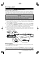
PACKET OPERATION The FT-1802M may be used for 1200 bps Packet operation, using most all commonlyavailable Terminal Node Controllers (TNCs). Connections between the transceiver and the TNC are accomplished via the front panel Microphone connector and rear panel External Speaker jack, per the diagram below. The audio level from the receiver to the TNC may be adjusted by using the VOL knob, as with voice operation.
MISCELLANEOUS SETTINGS PASSWORD The FT-1802M provides a password feature which can minimize the chance that your transceiver could be used by an unauthorized party. When the password feature is activated, the radio will ask for the four digit password to be entered when the radio is first turned on. You must enter the four digit password from the Microphone’s keypad. If the wrong password is entered, the microprocessor will shut down the radio automatically.
MISCELLANEOUS SETTINGS TIME-OUT TIMER (TOT) The “Time-Out Timer” (TOT) feature is designed to force the transceiver into the “receive” mode after a preset time period of continuous transmission (the default is 3 minutes). This feature prevents your transceiver from transmitting a “dead carrier” for a long period of time in the event that the microphone PTT switch is accidentally locked in the “TX” condition. The Time-Out Timer’s “switch-to-receive” time may be adjusted to 1/3/5/10 minutes, or Off.
MISCELLANEOUS SETTINGS BUSY CHANNEL LOCK-OUT (BCLO) The BCLO feature prevents the radio’s transmitter from being activated if a signal strong enough to break through the “noise” squelch is present. On a frequency where stations using different CTCSS or DCS codes may be active, BCLO prevents you from disrupting their communications accidentally (because your radio may be muted by its own Tone Decoder). The default setting for the BCLO is OFF, and here is how to change that setting: 1.
MISCELLANEOUS SETTINGS PROGRAMMING THE KEY ASSIGNMENTS Default FT-1802M key functions have been assigned to the Microphone’s [P1]/[P2]/[P3]/ [P4] buttons at the factory. These may be changed by the user, if you wish to assign quick access to another function. To change the assignments for the programmable keys: 1. Press and hold in the [MHz(SET)] key for one second, then rotate the DIAL knob to select the Menu Item to be configured (“36 PRG P1,” “37 PRG P2,” “38 PRG P3,” or “39 PRG P4”). 2.
MISCELLANEOUS SETTINGS FM BANDWIDTH & TX DEVIATION LEVEL You can reduce the receiver bandwidth and microphone deviation level when operating on tightly-clustered frequencies (channel spacing of 12.5 or 15 kHz). This will reduce the transmitter deviation, thus minimizing interference to other users. To configure for the narrower bandwidth, use the following procedure: 1. Press and hold in the [MHz(SET)] key for one second, then rotate the DIAL knob to select “59 W/N DV.” 2.
MISCELLANEOUS SETTINGS DCS CODE INVERSION The DCS system was first introduced in the commercial LMR (Land Mobile Radio) service, where it is now in widespread use. DCS is sometime referred to by its different proprietary names, such as DPL® (Digital Private Line®, a registered trademark of Motorola, Inc.). DCS uses a codeword consisting of a 23-bit frame, transmitted (subaudible) at a data rate of 134.4 bps (bit/sec).
RESET PROCEDURE In some instances of erratic or unpredictable operation, the cause may be corruption of data in the microprocessor (due to static electricity, etc.). If this happens, resetting of the microprocessor may restore normal operation. Note that all memories will be erased if you do a complete microprocessor reset, as described below. MICROPROCESSOR RESETTING To clear all memories and other settings to factory defaults: 1. Turn the radio off. 2.
CLONING The FT-1802M includes a convenient “Clone” feature, which allows the memory and configuration data from one transceiver to be transferred to another FT-1802M. This can be particularly useful when configuring a number of transceivers for a public service operation. Here is the procedure for Cloning one radio’s data to another: 1. Turn both radios off. 2. Connect the user-constructed cloning cable between the MIC jacks of the two radios. 3.
“SET” (MENU) MODE The FT-1802M Set (Menu) mode, already described in parts of many previous chapters, is easy to activate and set. It may be used for configuration of a wide variety of transceiver parameters, some of which have not been detailed previously. Use the following procedure to activate the Set (Menu) mode: 1. Press and hold in the [MHz(SET)] key for one second to enter the Set mode. 2. Rotate the DIAL knob to select the Menu Item to be adjusted. 3.
“SET” (MENU) MODE MENU ITEM 29 MW MD 30 NM SET 31 OPN.MSG 36 37 38 39 40 41 PRG P1 PRG P2 PRG P3 PRG P4 PSWD RESUME FUNCTION Selects the method of selection of channels for Memory Storage. Programming an Alpha/Numeric label for a Memory Channel. Selects the Opening Message that appears when the radio is powered on. Enables/Disables the Enhanced CTCSS Paging & Code Squelch function. Enables/Disables the Answer Back function of the Enhanced CTCSS Paging & Code Squelch function.
“SET” (MENU) MODE REPEATER SETTING SET MODE ITEM AVAILABLE VALUES (DEFAULT) Activates/Deactivates the Automatic Repeater Shift 4 ARS feature. Sets the Repeater Shift direction. 43 RPT Sets the magnitude of the Repeater Shift. 46 SHIFT CTCSS/DCS/EPCS SETTING ON / OFF –RPT / +RPT / SIMP 0.00-99.95 (MHz) (0.60MHz) SET MODE ITEM AVAILABLE VALUES (DEFAULT) Selects the CTCSS/DCS/EPCS Bell Ringer repeti- 7 BELL tions. Setting of the DCS code.
“SET” (MENU) MODE WIRES™ SETTING SET MODE ITEM AVAILABLE VALUES (DEFAULT) Selects the Access Number ( DTMF digit ) for WIRES™ operation. Selects the Internet Link Connection mode. Enables/Disables DTMF Autodialer feature while operating on the Internet Connection feature. Selects the memory register for an Access Number (DTMF code) for non-WIRES™ Internet Link System access. 22 INT CD SWITCH/KNOB SETTING SET MODE ITEM AVAILABLE VALUES (DEFAULT) Enables/Disables the key beeper.
“SET” (MENU) MODE MENU SELECTION DETAILS 1 APO Function: Enables/Disables the Automatic Power Off feature. Available Values: 30MIN / 1HOUR / 3HOUR / 5HOUR / 8HOUR / OFF Default: OFF 2 AR BEP Function: Selects the Beep option during ARTS operation. Available Values: IN RNG / ALWAYS / OFF Default:IN RNG IN RNG: Beeps sound only when the radio first detects that you are within range. ALWAYS: Beeps sound every time a polling transmission is received from the other station (every 15 or 25 seconds when in range).
“SET” (MENU) MODE MENU SELECTION DETAILS 8 BNK.LNK Function: Selects the Memory Bank(s) for the Memory Bank Link Scan. See page 46 for details. 9 BNK NM Function: Programming an Alpha/Numeric label for a Memory Bank. See page 39 for details. 10 CLK.SFT Function: Shifting of the CPU clock frequency. Available Values: ON / OFF Default: OFF This function is only used to move a spurious response “birdie,” should it fall on a desired frequency.
“SET” (MENU) MODE MENU SELECTION DETAILS 16 DIMMER Function: Setting of the front panel display’s illumination level. Available Values: 0 (OFF) - 10 Default: 5 17 DT A/M Function: Enables/Disables the DTMF Autodialer feature. Available Values: MANUAL / AUTO Default: MANUAL 18 DT DLY Function: Setting of the DTMF Autodialer’s TX Delay Time. Available Values: 50 / 250 / 450 / 750 / 1000 ms Default: 450 ms 19 DT SET Function: Loading of the DTMF Autodialer Memories. See page 32 for details.
“SET” (MENU) MODE MENU SELECTION DETAILS 24 INT.A/M Function: Enables/Disables DTMF Autodialer feature while using the Internet Connection feature. Available Values: MANUAL / AUTO Default: MANUAL 25 INT.SET Function: Selects the memory register for an Access Number (DTMF code) for non-WIRES Internet Link System access. Available Values: F0 - F9 Default: F1 26 LOCK Function: Selects the Control Locking Lockout combination.
“SET” (MENU) MODE MENU SELECTION DETAILS 30 NM SET Function: Programming an Alpha/Numeric label for a Memory Channel. See page 36 for details. 31 OPN.MSG Function: Selects the Opening Message that appears when the radio is powered on. Available Values: DC / MSG / OFF Default: DC DC: DC supply voltage MSG: Set by user. See below. OFF: No Opening Message Here’s how to program the Opening Message: 1. Set this Set Mode Item to “MSG.” 2.
“SET” (MENU) MODE MENU SELECTION DETAILS 35 PAG.CDT Function: Setting the Transmitting Pager Code for the Enhanced CTCSS Paging & Code Squelch function. See page 27 for details. 36 PRG P1 Function: Programming the function assigned to Microphone’s [P1] key. Available Values: ARTS / SQL OFF / WX CH / S SRCH / C SRCH / SCAN / T CALL or one of the all Set mode items (except Set mode item #36 through 39; initial setting is “Set mode item #13 DC VLT”).
“SET” (MENU) MODE MENU SELECTION DETAILS 41 RESUME Function: Selects the Scan Resume mode. Available Values: BUSY / HOLD / 3SEC / 5SEC / 10SEC Default: BUSY BUSY: The scanner will hold until the signal disappears, then will resume when the carrier drops. HOLD: The scanner will stop when a signal is received, and will not restart. 3SEC/5SEC/10SEC: The scanner will hold for the selected resume time, then resume whether or not the other station is still transmitting.
“SET” (MENU) MODE MENU SELECTION DETAILS 47 SKIP Function: Selects the Memory Scan mode. Available Values: SKIP / ONLY / OFF Default: OFF SKIP: The scanner will “skip” the flagged channels during scanning. ONLY: The scanner will only scan channels that are flagged (Preferential Scan List). OFF: All memory channels will be scanned (the “flag” will be ignored). 48 SPLIT Function: Enables/Disables split CTCSS/DCS coding.
“SET” (MENU) MODE MENU SELECTION DETAILS 52 TN FRQ Function: Setting of the CTCSS Tone Frequency. Available Values: 50 standard CTCSS tones Default: 100.0 Hz CTCSS TONE FREQUENCY (Hz) 67.0 69.3 71.9 74.4 77.0 82.5 85.4 88.5 91.5 94.8 79.7 97.4 100.0 103.5 107.2 110.9 114.8 118.8 123.0 127.3 131.8 136.5 141.3 146.2 151.4 156.7 159.8 162.2 165.5 167.9 53 TOT 171.3 173.8 177.3 179.9 183.5 186.2 Function: Sets the Time-Out Timer. 189.9 192.8 196.6 199.5 203.5 206.
“SET” (MENU) MODE MENU SELECTION DETAILS 59 W/N DV Function: Reduction of the Microphone Gain/Deviation and receiver bandwidth. Available Values: WIDE (±5 kHz Deviation, 15 kHz Bandwidth) / NARROW (±2.
NOTE 82 FT-1802M OPERATING MANUAL
NOTE FT-1802M OPERATING MANUAL 83
NOTE 84 FT-1802M OPERATING MANUAL
1. Changes or modifications to this device not expressly approved by VERTEX STANDARD could void the user’s authorization to operate this device. 2. This device complies with part 15 of the FCC Rules. Operation is subject to the following two conditions; (1) this device may not cause harmful interference, and (2) this device must accept any interference including interference that may cause undesired operation. 3.
Copyright 2005 VERTEX STANDARD CO., LTD. All rights reserved. No portion of this manual may be reproduced without the permission of VERTEX STANDARD CO., LTD.