C4FM/FM 144/430MHz DIGITAL/ANALOG TRANSCEIVER FT-70DR FT-70DE Operating Manual
Contents Introduction ............................................................... Quick Guide .............................................................. Controls & Connections .......................................... Transceiver ................................................................ The Keypad Functions ............................................... Display ....................................................................... Safety Precautions (Be Sure to Read) ....................
Introduction Thank you for purchasing this Yaesu product. PP The FT-70DR/FT-70DE is a handheld transceiver for operation in the 144 MHz and 430 MHz Amateur radio bands. It is compatible with the Analog FM and C4FM modes. PP The FT-70DR/FT-70DE is rugged and compact (W60 × H98 × D33 mm (2.36″ × 3.86″ × 1.30″)) providing splash, water, and dust resistant features conforming to IP54 for mobile and field operation.
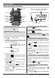
Quick Guide Names and display of Controls DIAL Knob Normal operation (VFO Mode) Operating Frequency PTT Switch Microphone MONI/T.CALL Switch [GM] key VOL Switch Power (Lock) Switch [MODE] key [F] key [BAND] key Volume Level S Meter / PO Meter Communication Mode Turning the Power ON Install the charged battery pack and then switch. press and hold the Inputting the Call sign When turning the power ON for the first time after purchasing, input the call sign of your own station.
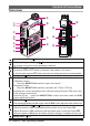
Controls & Connections Transceiver ⑨ ① ② ⑯ ⑩ ⑬ ③ ④ ⑤ ⑪ ⑥ ⑦ ⑫ ⑭ ⑧ ⑮ ⑧ * Antenna Jack (SMA) ( 12) LCD (Liquid Crystal Display) ( 6) The display shows the current operating conditions. PTT Switch ( 17) • Press and hold the PTT switch to transmit, and release it to receive. • In the Set mode, press the PTT switch to save the new setting and return to normal operation. Microphone ( 17) MONI/T.CALL Switch USA/Asian version Press the MONI/T.CALL switch to open the squelch.
DIAL Knob ( 15) • Rotate the DIAL Knob to change the frequency or select a memory channel. • While pressing and holding the VOL Switch, rotate the DIAL knob to adjust the audio volume level. • Rotate the DIAL Knob to select the desired entry for set mode. MODE/STATUS Indicator Indicates the transmit/receive status, and the communication mode with the high brightness LED.
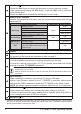
The Keypad Functions Key GM Primary Function (Press Key) VFO or Memory Recall Inputting Memory Tag Turns the GM (Group Press and hold this M o n i t o r ) f u n c t i o n key to erase all charON/OFF acters after the cursor Secondary Function (Press F + Key) Third Function (Press and Hold for over one second) - Turns the GM (Group Monitor) function ON/OFF Activates the “Sec- P r e s s t h i s k e y t o Deactivates the “Secondary” key function complete memory tag ondary”key function Enters the Set mode
Display Frequency / Memory Tag / Set Mode Item Memory Channel Number / HOME Channel / Memory Bank Number/ In Range / Out of Range (GM function) Volume Bar Graph Communication Mode DN: Normal digital mode VW: Voice wide mode FM: Analog FM mode AM: AM mode (Receive only) Icon S Meter:Displays the received signal strength PO Meter:Displays the transmit power level Description Appears when the GM (Group Monitor) function in the digital mode is enabled.
Icon Description : Appears when a function key is pressed. : On writing the memory channel, etc. Appears when the AMS (Automatic Mode Select) function is enabled. It is recommended that AMS function be enabled for normal operations. 5 25 16 TX Power Level Indicator (LOW/MID TX Power Selected) Tx Power HIGH (5 W ) Icon TX Power Meter during transmission (No display) 18 MID (2 W ) LOW (0.5 W ) Appears when the Dual Receive(DW) function is enabled.
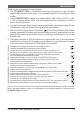
Safety Precautions (Be Sure to Read) Be sure to read these important precautions, and use this product safely. Yaesu is not liable for any failures or problems caused by the use or misuse of this product by the purchaser or any third party. Also, Yaesu is not liable for damages caused through the use of this product by the purchaser or any third party, except in cases where ordered to pay damages under the laws.
If smoke or a strange odor is emitted from the main body, battery pack, or battery charger, immediately turn the transceiver off; remove the battery pack, and remove the power plug from the outlet. A fire, chemical leak, overheating, component damage, ignition, or failure may result. Contact the dealer from which you purchased this product or Yaesu Amateur Customer Support. Do not bend, twist, pull, heat and modify the power cord and connection cables in an unreasonable manner.
Keep magnetic cards and videotapes away from the transceiver. The data recorded on cash cards or videotapes may be erased. Do not place this transceiver in direct sunlight or near a heater. The case may be deformed or discolored. Be sure to check with the manufacturer of any hybrid or fuel-saving automobile regarding use of the transceiver in that car. Noise generated by an onboard electrical device (inverter, etc.) can disrupt the normal operation of the transceiver.
About this manual Reference icon symbols and conventions are used in this manual. Their meanings are described in the below chart. Symbols Description This icon indicates cautions and information that should be read. This icon indicates notes, tips and information that should be read. This icon indicates other pages containing relevant information. This icon indicates FT-70DR/DE Advance Manual on the YAESU Website containing relevant information.
Preparation Installing the Antenna 1. Turn the antenna clockwise until it is secured. zz Do not hold or twist the upper part of the antenna when installing or removing it. To do so may break the conductors inside the antenna. zz Do not key the transmit without installing the antenna. The transmitter components may be damaged. zz When using an antenna other than the one supplied, or connecting to an external antenna, ensure that the SWR is adjusted to 1.5 or lower.
Charging the Battery Pack Charging the Battery Pack using the Battery Charger Using the supplied battery charger (SAD-18B or SAD-11), it takes about 6 hours* to charge the SBR-24LI battery pack fully. *: Depending on the battery status, the charging time might be increased. 1. Turn the transceiver OFF to install the battery pack. 2. Referring to the figure at the right, connect the battery charger plugs.
Operation Turning the Transceiver ON 1. Press and hold the Power (Lock) switch to turn the transceiver ON. ●● Turning the transceiver OFF Press and hold the Power (Lock) switch again to turn the transceiver OFF. ●● Inputting the call sign The first time the transceiver is turned ON after it is purchased; input your own call sign. zzInputting characters Input the callsign with the ten key or DIAL knob. • Rotate the DIAL knob to select any of the 38 available characters:.
Adjusting the squelch setting The squelch level may be adjusted to mute the background noise when no signal is present. 1. Press the [F] key and then press the MONI/T-CALL switch. “SQL □” (0 - 15) appear on the display. 2. Rotate the DIAL knob to adjust to a level at which the background noise is muted. 3. Press the PTT switch to save the setting.
Selecting the Communication Mode Using AMS (Automatic Mode Select) function The FT-70DR/DE transceiver is equipped with the AMS (Automatic Mode Select) function which automatically selects the communication mode corresponding to the received signal. 1. Press and hold the [AMS] key to turn the AMS function ON or OFF. When the AMS function is turned OFF, the communication mode must be selected manually. See "(Fixing the Communication Mode)". The selected communication mode is displayed under the AMS icon.
Fixing the Communication Mode 1. To fix the transmit operation mode, press and hold the [AMS] key to turn the AMS function OFF. The “AMS” icon turns off. 2. Press the [MODE] key to change the commuication mode. Communication Mode Icon Description of Modes V/D Mode (Voice/Data simultaneous transmission mode) This is the standard digital mode. Calls are less prone to interruptions caused by detection and correction of the received digital voice signal.
Changing the Transmission Power Level 1. Press the [F] key, then press the [1](TX PO) key. 2. Rotate the DIAL knob to select one of the following transmission power levels. TX PO Level HIGH (5 W)* MID Icon (off) PO meter (2 W) LOW (0.5 W) *The default setting. 3. Press the PTT switch to save the setting and return to the normal operation. The transmission power level may be set separately for each frequency band. Locking Keys and DIAL knob 1.
Using the convenient Digital C4FM feature About the Digital Group ID (DG-ID) feature 1. Digital Group ID (DG-ID) function allows communications with only the specific group members using the two-digit ID numbers. The desired DG-ID number from 00 to 99 is set in advance by all the group members. This ID number may be set separately for transmit and receive, when the same ID number is set for both transmit and receive, only group members with the same ID number will be heard.
4. To check whether or not other stations are operating within communications range, press the [GM] key to turn the GM (Group Monitor) function ON. • The other stations also need to turn the GM (Group Monitor) function ON. • While operating with the GM (Group Monitor) function, “Operating Frequency”, “GROUP” and “DG-ID number” are shown repeatedly on the LCD. 5. Press the [GM] key to turn the GM (Group Monitor) function OFF and return to the normal operation.
For example, if the transmit and receive DG-ID numbers of group members are all set to "50", communications from other DG-ID numbers is not received and only the group members setting the same DG-ID numbers may communicate. Also, the other stations set the receive DG-ID to any number except for "00" may not be received the signals of your stations.
●● In / Out Display • When another station with the same DG-ID number is within the communication range, a beep sounds and the "In" is displayed under the GM (Group Monitor) function icon, and the right side of the MODE/STATUS indicator lights in light blue. • When all the members are out of the communication range, "out" is displayed and the MODE/STATUS indicator light is off.
Repeater Operation Communicating Via the Repeater The transceiver includes an ARS (Automatic Repeater Shift) function which sets the repeater operation automatically when the receiver is tuned to the repeater frequency. 1. Set the downlink (output) frequency from the reRepeater shift icon Tone encoder icon peater. 2. “ ”, “ ”or “ ” lcons may automatically appear above the frequency. 3. Speak into the microphone while pressing and holding the PTT switch.
Using the Memory The FT-70DR/DE transceiver incorporates Large-capacity memory channels that can register the operating frequency, communication mode, and other operational information. • 900 Memory Channels • 90 Skip Search Memory Channels • 6 Home Channels • 50 pairs PMS Memory Channels Each memory channel can store the following information.
Registering to Memory Channels 1. Set the frequency and the communication mode to be registered to a memory channel. 2. Press the [V/M] key. “ ” blinks on the LCD. 3. Rotate the DIAL knob to select the desired channel number. The channel numbers that do not contain memory data will blink on the LCD. 4. Press the [V/M] key. • If you attempt to register a frequency to a memory channel that already contains frequency data, “M-WRT?” will appear on the LCD. Press the [ V/M ] key to overwrite the memory channel.
Clearing Memories 1. Press the [V/M] key to enter the memory mode. 2. Press and hold the [V/M] key. 3. Rotate the DIAL knob to select the memory channel from which the data is to be cleared. 4. Press the [AMS] key. 5. Confirmation screen “M-MSK?” is displayed and then press the [AMS] key again to clear the memory channel. zz Data on memory channel One, and the Home channel may not be cleared. zz The cleared memory can be restored using the following steps.
Scanning Function The transceiver supports the following four scanning functions: • VFO Scan • Memory Channel Scan • Programmable Memory Scan (PMS) • Memory Bank Scan • Weather Alert Scan (USA Version only) For additional details on the Programmable Memory Scan (PMS) and Memory Bank Scan, refer to the Advanced Manual which may be downloaded from the Yaesu website. VFO Scan VFO scan function scans the frequencies, and detects signals. 1. Press the [V/M] key to enter the VFO mode. 2.
Setting the Receive Operation When Scanning Stops Press and hold the [F] key to enter the Set Mode. Rotate the DIAL knob to select the Set Mode [52 SCN.RSM]. Press the [F] key. Rotate the DIAL knob to select the operation performed after the scan stops: • 2.0 S - 10.0 S The signal is received for a specified period of time, and then scanning resumes. The scan resume time may be set from 2 to 10 seconds at 0.5 second intervals. • BUSY The signal is received until the signal fades out.
6. While scanning the Weather channels, press the PTT switch and then press the PTT switch again. • Scanning starts within the Weather Broadcast Channels. • While scanning the Weather channels, press the PTT switch and then rotate the DIAL knob to select the desired Weather Broadcast Channel. 7. Press the [V/M] key return to normal operation. CH Frequency A1 162.550 MHz A2 162.400 MHz A3 162.475 MHz A4 162.425 MHz A5 162.450 MHz A6 162.500 MHz A7 162.525 MHz A8 161.650 MHz A9 161.
Using the WIRES-X Function WIRES-X feature WIRES (Wide-coverage Internet Repeater Enhancement System) is an Internet communication system which expands the range of amateur radio communication. You may employ Internet communications by connecting from your transceiver to a WIRES-X local node station. FT-70DR/DE does not accommodate the transmission/reception of messages, images, audio messages, or location information.
zzAfter successfully connecting to the node, one of the following screens (Lc / Cn) is displayed indicating the node status. Node ID screen (the Node Lc screen) • This screen is displayed if the node is disconnected from the other node or the room on the Internet. • The local node station’s node ID is displayed.
Registered node ID or room ID screen (the C1 - C5 screen) • Rotate the DIAL knob to select a previously registered node/room (maximum 5 nodes/rooms) on the C1 - C5 screen and, then press the [AMS] key or PTT switch to connect to the node/room. • Registering the node/room: Press and hold the [1] - [5] key to register the node/room (C1 - C5) on the connected node ID or room ID screen (Cn).
Press and hold the [1] to [5] key (Cn screen) The connected node or room ID is registered to the memory of the number when it is pressed and held (In case the memory is already written, the registration is overwritten). Press the [V/M] key (On activating WIRES-X) Temporarily displays the operating frequency (when calling C4FM digital signal, the callsign of the other station is displayed). Press the [V/M] key again to return to the previous screen. 8.
Convenient Functions For additional details on the following functions, refer to the Advanced Manual which may be downloaded from the Yaesu website. Tone squelch feature The tone squelch opens the speaker audio only when a signal containing the specified CTCSS tone is received. By matching the tone frequency with the partner station in advance, a quiet standby is possible.
Using Set Mode The Set Mode permits configuring the various functions according to individual operating needs and preferences. 1. Press and hold the [F] key. The previously selected Set Mode item is displayed. 2. Rotate the DIAL knob to select the desired Set Mode item. 3. Press the [F] key and then rotate the DIAL knob to change the setting. 4. Press the PTT switch to save the settings and return to normal operation. On some setting screens, pressing the PTT switch does not exit from Set mode.
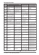
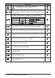
Tables of Set Mode Operations No. Set Mode item 1 ANT.ATT Selectable options (Options in bold are the default settings) Description Switch the attenuator between ON/OFF. OFF / ON Set the length of time until the transceiver OFF / 0.5 Hours to 12 Hours turns off automatically. 2 APO 3 BCLO Turns the busy channel lockout function on/off. OFF / ON 4 BEEP Sets the beep sound function. OFF / KEY+SC / KEY 5 BEP.LVL Beep volume setting LEVEL1 – LEVEL4 – LEVEL7 6 BEP.
Selectable options (Options in bold are the default settings) No. Set Mode item 32 M/T-CL 33 MEM.NAM Input the memory channel tag. 34 MW MOD Set the automatic channel number increment LOWER / NEXT when registering to a memory channel. 35 NM/FRQ Select the memory channel tag display or FREQ / ALPHA frequency display 36 OPN.MSG Select the Opening Message that appears OFF / MSG / DC when the transceiver is ON.
Restoring to Defaults (Reset) All Reset To restore all transceiver settings and memory content to the factory defaults. CAUTION! Resetting the transceiver will clear all memories. Please make a note of the memories (memory channel settings, etc) before resetting. 1. T urn the transceiver OFF. 2. Press and hold the [MODE] key, the [HM/RV] key and the [AMS] key and turn the transceiver ON simultaneously. The beep sounds and the confirmation screen is displayed. 3. Press the [F] key.
Specifications ●● General Frequency Range : RX 108-137 MHz 137-174 MHz 174-222 MHz 222-420 MHz 420-470 MHz 470-580 MHz TX Channel Steps: Mode of Emission: Frequency Stability: Antenna Impedance: Supply Voltage: Current Consumption(Approx.): Operating Temperature: Case Size (W × H × D): Weight (Approx.
●● Receiver Circuit Type: Intermediate Frequency: Sensitivity: Double-conversion super heterodyne 1st: 47.25 MHz 2nd: 450 kHz 108 - 137 MHz (AM) 1.5 μV typ @10 dB SN 137 - 174 MHz (NFM) 0.16 μV @12 dB SINAD 174 - 222 MHz (NFM) 1 μV @12 dB SINAD 300 - 350 MHz (NFM) 0.5 μV @12 dB SINAD 350 - 400 MHz (NFM) 0.2 μV @12 dB SINAD 400 - 470 MHz (NFM) 0.18 μV @12 dB SINAD 470 - 580 MHz (NFM) 0.35 μV @12 dB SINAD Digital Mode 0.
zz Changes or modifications to this device that are not expressly approved by YAESU MUSEN could void the user’s authorization to operate this device. zz This device complies with part 15 of the FCC Rules. Operation is subject to the following two conditions: (1) This device may not cause harmful interference, and (2) this device must accept any interference including received, interference that may cause undesired operation.
Copyright 2018 YAESU MUSEN CO., LTD. All rights reserved. No portion of this manual may be reproduced without the permission of YAESU MUSEN CO., LTD. YAESU MUSEN CO., LTD. Tennozu Parkside Building 2-5-8 Higashi-Shinagawa, Shinagawa-ku, Tokyo 140-0002 Japan YAESU USA 1809R-CY Printed in Japan 6125 Phyllis Drive, Cypress, CA 90630, U.S.A. YAESU UK Unit 12, Sun Valley Business Park, Winnall Close Winchester, Hampshire, SO23 0LB, U.K.