
Operation Manual
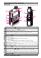


5FT-70DR/FT-70DE Operating Manual
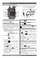
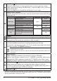
The Keypad Functions
Key
Primary Function
(
Press Key
)
Secondary Function
(
Press F + Key
)
Third Function
(
Press and Hold for
over one second
)
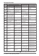
VFO or Memory Recall Inputting Memory Tag
GM
Turns the GM
(
Group
Monitor
)
function
ON/OFF
Press and hold this
key to erase all char
-
acters after the cursor
-
Turns the GM
(
Group
Monitor
)
function
ON/OFF
Activates the “Sec-
ondary” key function
(
appears
)
Press this key to
complete memory tag
in the Set Mode
Deactivates the “Sec-
ondary”key function
(
disappears
)
Enters the Set mode.
MODE
Selects the receive
mode between
FM
(
AM
)
, DN and VW*
Moves the cursor to
the left.
Switches between the
frequency display and
the memory tag display
Sets the DG-ID number
HM/
RV
Reverses the transmit
and receive frequen
-
cies while working
through a repeater
-
Recalls the “HOME”
(
favorite frequency
)
channel
Overwrites the “HOME”
(
favorite frequency
)
channel
AMS
Selects AMS Mode
(
TX
AUT/TX FM/TX DIG
)
-
Activates the
WIRES-X feature
Activates the AMS
feature
BAND
(
BND DN)
Moves operation to
the next-highest fre-
quency band
Moves the cursor to
the right
Moves operation to
the next-lowest fre-
quency band
-
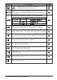
V/M
(
DW)
Switches between the
VFO mode and the
Memory Channel mode
Press and hold this key
to complete the memo-
ry channel registration
Enables the Dual Re-
ceive function
Activates the “Memory
Write” mode
(
for mem-
ory channel storage
)
1
(
TX PO
)
Number “1” Number “1”
Selects the desired
transmit power output
level.
Enters all the zeros at once
after entering the number “1”
on inputting the frequency.
2
(
SCAN
)
Number “2”
Number “2”, or char-
acters “A”, “B”, or “C”
Starts the scanning
Enters all the zeros at once
after entering the number “2”
on inputting the frequency.
3
(
DTMF
)
Number “3”
Number “3”, or char-
acters “D”, “E”, or “F”
Selects the DTMF mode.
Enters all the zeros at once
after entering the number “3”
on inputting the frequency.
4
(
STEP
)
Number “4”
Number “4”, charac-
ters “G”, “H”, or “I”
Selects the frequency
steps
Enters all the zeros at once
after entering the number “4”
on inputting the frequency.
5
(
SQ TYP
)
Number “5”
Number “5”, charac-
ters “J”, “K”, or “L”
Selects the squelch
types
Enters all the zeros at once
after entering the number “5”
on inputting the frequency.
6
(
CODE
)
Number “6”
Number “6”, or char-
acters “M”, “N”,or “O”
Selects the CTCSS
Tone or DCS code
enters all the zeros at once
after entering the number “6”
on inputting the frequency.
7
(
P1
)
Number “7”
Number “7”, or char-
acters “P”, “Q”, “R”, or
“S”
P1
(
programmable
key 1
)
enters all the zeros at once
after entering the number “7”
on inputting the frequency.
8
(
P2
)
Number “8”
Number “8”, or char-
acters “T”, “U”, or “V”
P2
(
programmable
key 2
)
enters all the zeros at once
after entering the number “8”
on inputting the frequency.
9
(
SKIP
)
Number “9”
Number “9”, or char-
acters “ W ”, “X”, “Y”,
or “Z”
Selects the Memory
Scan “Skip” channel
or “Select” channel
enters all the zeros at once
after entering the number “9”
on inputting the frequency.
0
(
RPT
)
Number “0”
Number “0”, or sym-
bols“
(
space
)
”, “-”, “/”,
“?”, or “!”
Selects the direction of
the up link frequency shift
(
either “–”, “+”, or “simplex”
)
during repeater operation.
enters all the zeros at once
after entering the number “0”
on inputting the frequency.
*: VW icon is displayed when Set Mode
[
16 DIG VW
]
(
36
)
is set to “ON”
(
the default setting is “OFF”
)
.