Yale 7402 2 Wire Video Intercom System USER MANUAL User Setup (1) Door Station Call Tone ... Intercom Call Tone ... DoorBell Tone ... Clock ... Next Page ...
Power Unit 1. Warning - Don’t dismantle or alter the unit. Fire or electric shock could result. - The unit must be installed and wired by a qualified technician. - Do not connect any non specified power source to the N, L terminals, Fire, damage to the unit, or system malfunciont can result. - Keep the unit away from water or any other liquid, risk of fire or electric shock. 2. Introduction: The power unit is designed for two wire systems.
4. Mounting: Step1: Mount the din rail to the wall with screws ; Step2: Pull down the lock release lever,then hang the unit on din rail. Din rail Din rail Lock release lever 5. Basic wiring (no lock): 2 BUS BUS (DS) (IM) NP NP: Non-polarized PA P- P+ L1 L2 N L 2 NP L1 L2 AC~ Note:PA&P+ terminal must be short-circuited. Input Voltage: Input Frequency: Rated Output Voltage: Rated Output Current: Working Temperature: SW Port Input Voltage: Dimension: 100~240Vac 50~60Hz DC 28V+/-2V 1.
Exterior Unit 1.Parts and Functions Camera Lens Speaker 176 mm Night View LED Nameplate Call Button Microphone Rain Cover 90 mm 23 mm 2.
• Lock Control Jumper: Not to be removed • Doorstation Code DIP: To be used when additional exterior units are used in the same system. • Main Connect Port: To connect the interior monitor and electornic lock/s. BUS: Connection to interior monitor, no polarity. PL: External lock power input, connect to the power positive(power +). S1+, S2+: Lock power(+) output. To locks can be connected through the unit.
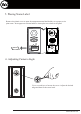
5. Placing Name Label Remove the plastic cover to open the transparent name label holder, cut a paper to size print name. Insert paper on to name holder re insert plast cover back to the panel ON 1 2 Backside name label 6. Adjusting Camera Angle Use a screwdriver to loosen the screw. Adjust the desired anlge and then fix the screw back.
. Basic wiring (with electronic lock) ON 1 2 AC~ monitor BUS(IM) BUS(DS) BUS(DS) BUS PLS1+ S2+ S- BUS(IM) + Use supplied plugs to connect Exterior unit to Power unit, and Power Unit ot Interior Monitor.
Interior Monitor 1. Parts and Functions Digital TFT LCD screen UNLOCK(▲) button MONITOR(▼) button INTERCOM(●) button TALK(◄) button MENU(►) button Microphone Mounting hook Speaker Connection Port BT1 BT2 EH GND VD DIPS ON 1 2 3 4 5 6 L1 L2 Mounting hook 145~160 cm 2. Monitor Mounting 1. Use the scrwes to fix the mounting bracket on the mounting box. Fitting accesories include a bracket (Two 4X25 screws are needed for fastening the mouting bracket), 2 wire adaptor to connect with Monitor and cable.
3. Basic Door Release Operation 1. Press CALL button on outdoor station, the Monitor rings, at the same time, the screen displays the visitor image. DS-1 00:23 2. Press TALK ( ) button on monitor, you can communicate hands free with the visitor for 90 seconds.After finishing communication,press "TALK" button again to end the communication. If nobody answers the phone, the screen will be turned off automatically after 30 seconds. UNLOCK ( ) button to open the door for the 3.
Intercom Call : User in one apartment can call Intercom Call other apartments in the system. The namelist will be [ 00 ] Alex [ 01 ] Joe created automatically by the system. Selete a name [ 02 ] Ray [ 03 ] Alice [ 04 ] Mary on the screen then press MENU ( ) button to [ 05 ] Martin dial.(Note 1. Press "MENU " button again to redial. Last/Next Exit Calling 2.
6. Date and Time Setting Select Clock... item on User Setup (1) page. Input date and time by pressing ▲ / ▼ button to increase / decrease the value; press / button to select last/next digit. Press INTERCOM ( ) button to save and return last page. Clock 2011- 04 - 22 17:17 Inc/Dec Last/Next Save&Exit 7. Advanced Settings How to enter the advanced installation setting page step1 step2 step3 User Setup (1) 04/22/2011 03:25 Fir PM 1. Press 2. Press 3.
How to set secundary/slave monitors to view image when call is made In default mode and when receiveing a call, the master and slave monitors will ring at the same time, but just the master monitor will display the image, while the slave monitors will not. This setting can be changed to have all the monitors (master and slave), dispaly the image at the same time while receiving a call by using the code 8006 on each slave monitor. How to set the unlock lock mode Two types of unlock modes: 1.
Language mode setting This monitor can support multi languages. T o c h a n g e t h e l a n g u a g e , input the corresponding language code. The language code number are as follows: 8101: English 8102: French 8103: Spanish 8104: Italian 8105: German 8106: Dutch 8107: Portuguese 8108: S-Chinese 8109: T-Chinese 8110: Greek 8111: Turkish 8112: Polish 8113: Russian 8114: Slovakia 8115: Hungray 8116: Czech Note:the monitor can only support 4 types of languages.English,French,Spanish and German are default.
9. Monitor Time Setting While in monitoring mode, press INTERCOM button and use ▲ / ▼ to navigate to Monitor Time Set Option. Press MENU button to enter. Use ▲ / ▼ button to increase/decrease value and MENU button to save Monitor Time Select Current : Last/Next 01min Cancel Save&Exit 10. Specification ● Power supply for indoor monitor: DC24V ● Power consumption: Standby 0.